Hydraulic Pressure Control Apparatus and Hydraulic Circuit

Active Publication Date: 2008-10-23
TOYOTA IND CORP +1
View PDF5 Cites 2 Cited by
  • Summary
  • Abstract
  • Description
  • Claims
  • Application Information

AI Technical Summary

Benefits of technology

[0004]Accordingly, it is an objective of the present invention to provide a hydraulic pressure control apparatus that simplifies the configuration of a load pressure

Problems solved by technology

This complicates the configuration of the load pressure detection circuit.
Further, a relatively large space is required for arranging the load pressure detection circuit in a housing in which the direction switch valve is incorporated, thus enlarging the housing.
Also, in the apparatus of Japanese Laid-Open Patent Publication No. 2004-19873, the check valve must be a

Method used


Image

  • Hydraulic Pressure Control Apparatus and Hydraulic Circuit
  • Hydraulic Pressure Control Apparatus and Hydraulic Circuit
  • Hydraulic Pressure Control Apparatus and Hydraulic Circuit

Examples


Embodiment Construction

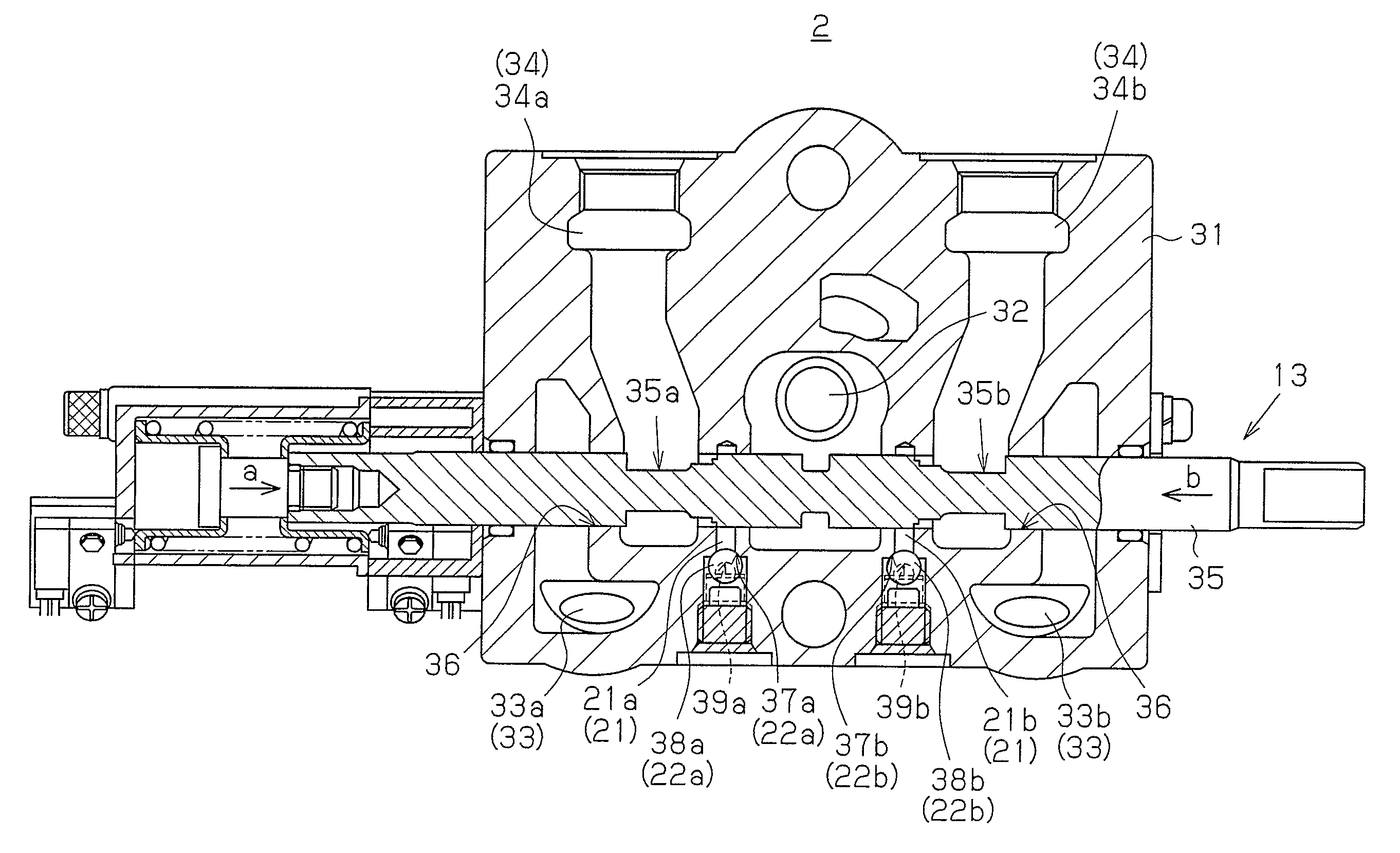
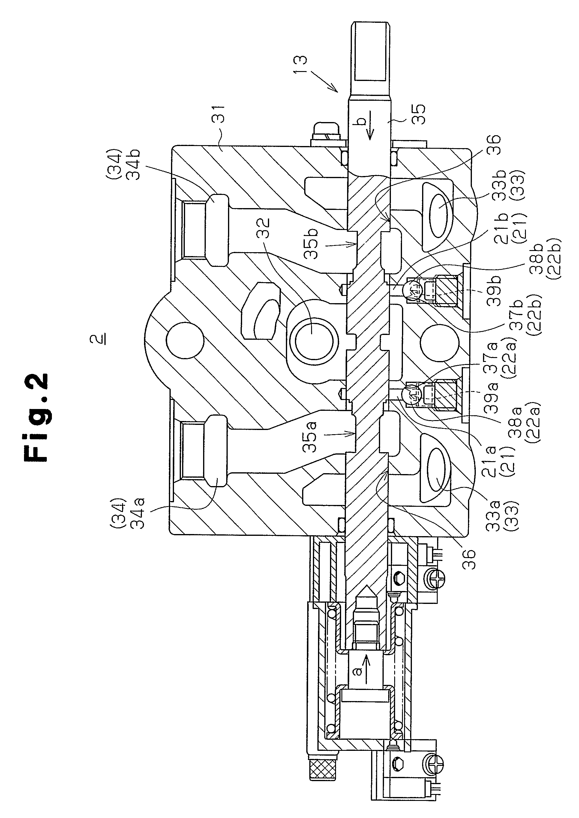
[0011]An embodiment of the present invention will now be described with reference to the attached drawings. The embodiment may be applied generally to hydraulic pressure control apparatuses having direction switch valves for controlling supply and drainage of hydraulic fluid to and from hydraulic actuators, which are spool valves. The spool valves are switched between at least two positions in correspondence with movement of spools. The embodiment may also be applied generally to hydraulic circuits including the aforementioned hydraulic pressure control apparatuses. In the following description, the embodiment is applied to, by way of example, a hydraulic circuit formed in a forklift for driving different hydraulic actuators serving as loading devices and hydraulic pressure control apparatuses provided in the hydraulic circuits. However, the present invention is not limited to such applications.

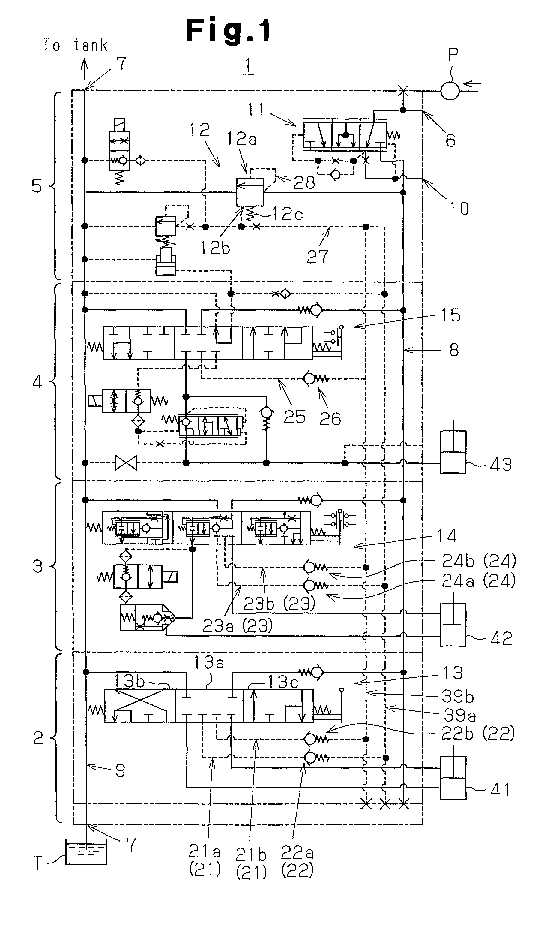
[0012]FIG. 1 is a diagram representing a hydraulic circuit 1 of the illustrated embodimen...


PUM


Abstract

A supply passage 32, a discharge passage 33, an actuator passage 34, and a spool bore 36 are defined in a housing 31. The spool bore 36 accommodates a spool 35 and communicates with the supply passage 32, the discharge passage 33, and the actuator passage 34. Load pressure detection circuit sections 21a, 21b of load pressure detection circuit 21 are provided in correspondence with switch positions 13b, 13c. Each of the load pressure detection circuit sections 21a, 21b detects load pressure when the actuator passage 34 is connected to the supply passage 32. Each load pressure detection circuit section 21a, 21b is defined by a through hole provided in the housing 31 and connected to the spool bore 36. Check valves 22 are each arranged in a corresponding one of the load pressure detection circuit sections 21a, 21b. This simplifies the configuration of each load pressure detection circuit 21 and saves the space for arranging the load pressure detection circuit 21. As a result, the housing 31 in which the load pressure detection circuit 21 is defined becomes relatively compact.

Description

TECHNICAL FIELD[0001]The present invention relates to hydraulic pressure control apparatuses having direction switch valves for controlling supply and drainage of hydraulic fluid to and from hydraulic actuators, which are spool valves switched between at least two positions in correspondence with movement of spools, and hydraulic circuits including the hydraulic pressure control apparatuses.BACKGROUND ART[0002]Conventionally, hydraulic pressure control apparatuses having direction switch valves for controlling supply and drainage of hydraulic fluid to and from hydraulic actuators, which are spool valves, are known. A typical spool valve is switched between at least two positions in correspondence with movement of a spool. For example, Japanese Laid-Open Patent Publication Nos. 3-172602 and 2004-19873 each describe one such apparatus having a load pressure detection circuit for detecting load pressure in correspondence with operation of a direction switch valve. Also, the hydraulic p...

Claims


Application Information

Patent Timeline
IPC IPC(8): F15B11/08F16D31/02
CPCF15B13/0402F15B13/0417F16K11/0708F15B13/04
Inventor MATSUZAKI, TAKEHARUNAKAJIMA, SHIGETO
Owner TOYOTA IND CORP
Why Eureka
Try Eureka