Electronic marking of a medication cartridge

a technology of electronic marking and medication cartridges, which is applied in the field of electronic marking of medication cartridges, can solve the problems of deteriorating the readability of optically readable or electronically readable coded information, robust marking methods, and not allowing the introduction of errors in the interpretation of coded information

Inactive Publication Date: 2009-11-10
NOVO NORDISK AS
View PDF192 Cites 52 Cited by
  • Summary
  • Abstract
  • Description
  • Claims
  • Application Information

AI Technical Summary

Benefits of technology

[0019]Thus, the object of the present invention is to provide an improved method of marking a medium.

Problems solved by technology

This method has the setback that either a relatively expensive chip is needed in the marked object or otherwise it does not provide any information on the content, the expiry date etc, of the container, it only tells whether the object is passing a certain location or not.
The possible spill of drops of the medication from the medication cartridge may typically deteriorate the readability of the optically readable or electronically readable coded information on the cartridge due to chemical reactions.
This calls for a method of marking which is robust and does not allow the introduction of errors in the interpretation of the coded information in case of minor deteriorations of the code in question.
If the conductive structures are placed on the label on top of the text, the reading of the printed text is likely to be disturbed.
For reasons which are described below it is not possible to increase the size of the label.
A restricted information carrying area increases the information density of the marking and therefore increases the demand for the mechanical precision of the coupling between the marking and the contact array.
These demands can be difficult to meet on mass produced cartridges, carpules or packages.

Method used


Image

  • Electronic marking of a medication cartridge
  • Electronic marking of a medication cartridge
  • Electronic marking of a medication cartridge

Examples


example 1

[0173]One way to carry out the marking of the cartridges is described in the following. A printing facility receives clear, transparent polyester foil delivered in rolls from a supplier. The polyester is delivered with clear adhesive and a protective paper carrier applied on the backside of the polyester foil. The adhesive is strongly attached to the polyester and is weakly attached to the carrier paper. This makes it possible to separate the polyester with the attached adhesive from the carrier paper and later to apply and attach the polyester to the surface of a product. In one process line the written information and the conductive polymer are applied on the frontside of the polyester foil by a suitable printing technique such as screen printing or rotaflex printing. Also, the roll of polyester is cut into separate labels by knife tools that only penetrate and cut the polyester but not the carrier paper. These finished adhesive labels on a carrier paper roll are obtained. The tex...

example 2

[0174]A printing facility produces a roll of labels with text printed onto it and with adhesive and carrier paper on the backside. This roll is referred to as the first roll. The first roll is equivalent to example one, however the conductive structures have not been applied on it. The front side of a second roll of clear polyester is covered entirely with indium tin oxide (ITO) in a suitable plasma coating facility, for example as found at Fraunhofer Institut for Electronenstrahl und Plasmatechnik, Dresden, Germany. The second roll is structured by means of aqueous etching as it is known from manufacturing of flexible electronic wireboards, as produced by Mekoprint, Randers, Denmark and many others. The structuring is accomplished by covering the second roll by resist applied by screen printing and then leading the roll through etching processes comprising etching of the part of the indium tin oxide coating, which is not covered by resist, in a solution of hydrochloric acid and cup...

example 3

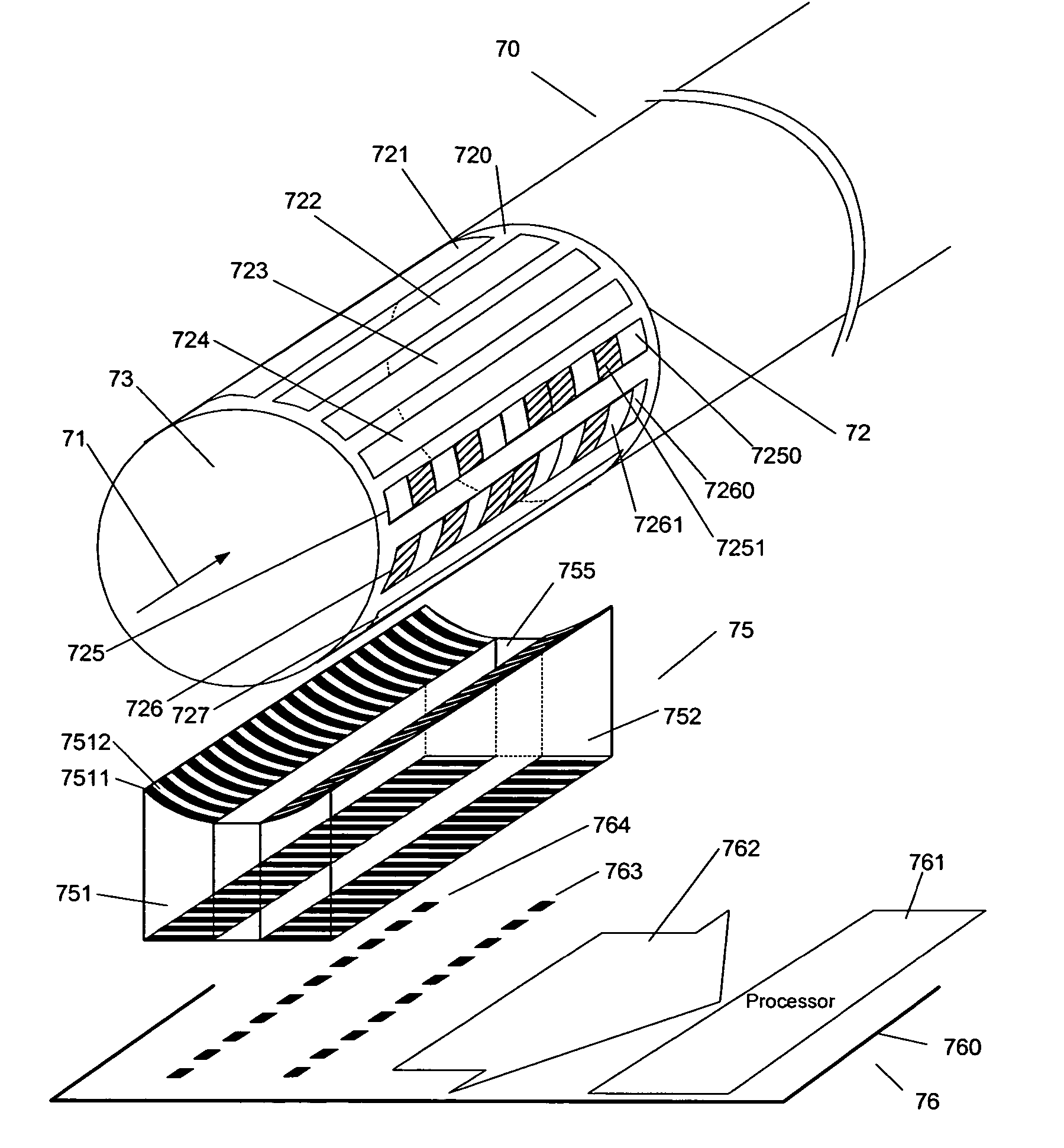
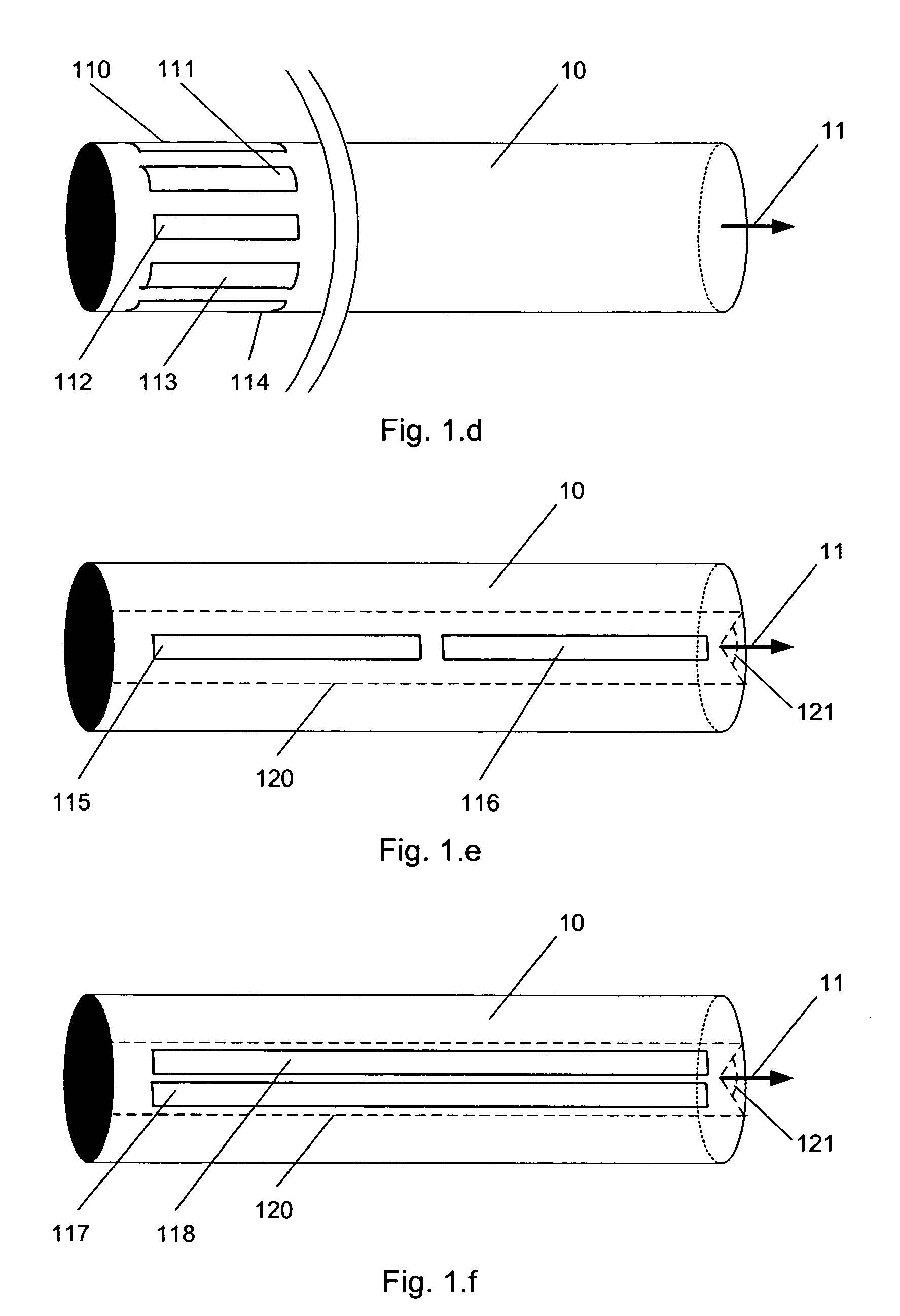
[0175]In the following text height and vertical direction of structures on the cylindrical surface of the cartridge and the contact array refer to an axis that follows the round-going circumference of the cylinder, whereas width and horizontal directions refer to an axis that follows the cylindrical axis, as indicated on FIG. 21.

[0176]A cell on the cartridge surface is defined to have the following dimensions:[0177]Height= 1 / 16 of the circumference=π*11.2 mm divided by 16=2.2 mm[0178]Width=7.5 mm

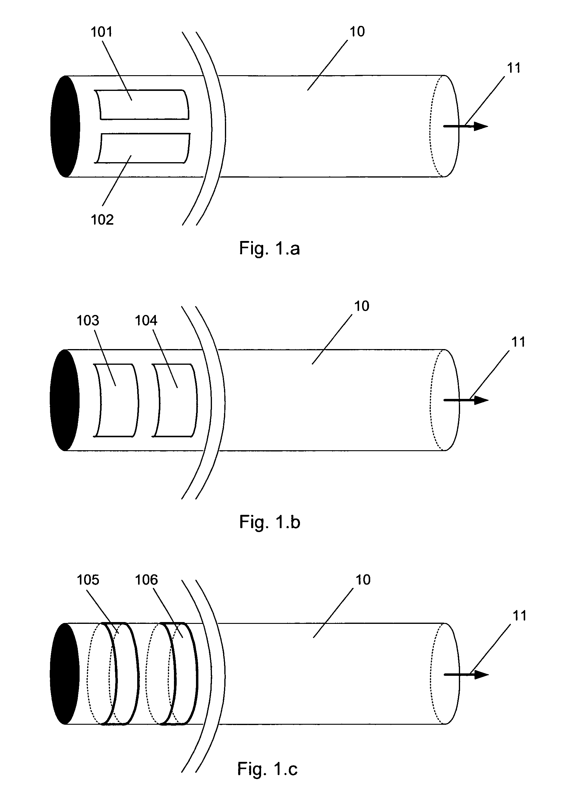
[0179]One cell can contain one bit of information. The bit value depends on how the conductor is printed in the cell. The conductor in FIG. 9 is an example of the bit-value ONE. FIG. 10 is an example of the bit-value ZERO. Three columns of 16 cells are distributed around the circumference of the cartridge, as shown in FIG. 11. The height of the cell ensures that the lower boundary of the first cell is essentially placed at the upper boundary of the 16th cell.

[0180]The matrix with 3 times 16 ...


PUM


Abstract

The invention relates to a marking of cartridges, carpules or any kind of package. The marking can be in an electronically readable form while being transparent. Hereby a marking with improved security for avoiding reading errors which ensures a mandatory visual inspection of content is obtained. The transparent conductor can be in form of a polymer, an ITO and the like. These transparent conductors are used in an improved marking technique, which further improves reading security. The invention may e.g. be used in connection with medication delivery devices for self-treatment of a disease, e.g. diabetes.

Description

CROSS-REFERENCE TO RELATED APPLICATIONS[0001]This application is a continuation of International Patent Application PCT / DK2004 / 000199 (published as WO 2004 / 084795), filed Mar. 23, 2004, which claimed priority of Danish Patent Application PA 2003 00448 filed, Mar. 24, 2003; this application further claims priority under 35 U.S.C. § 119 of U.S. Provisional Application No. 60 / 457,180 filed Mar. 25, 2003.THE TECHNICAL FIELD OF THE INVENTION[0002]The invention relates to the electronic marking of medication cartridges or the like.[0003]The invention relates specifically to: A medium such as a cartridge, a carpule, a label or a package provided with one or more electronically readable information carrying areas.[0004]The invention also relates to: A method of providing an electronically readable item of information on a medication cartridge.[0005]The invention furthermore relates to: A medication cartridge with an information-providing source containing an electronically readable item of ...

Claims


Application Information

Patent Timeline
Patent Type & Authority Patents(United States)
IPC IPC(8): G06K19/00G06K19/06G06K7/08G06K7/10A61J1/06A61M5/24G06K1/12G06K7/06G06K19/067G09F3/00G09F3/02
CPCA61J1/06A61M5/24G09F3/00G06K1/12G06K7/065G06K19/067A61M2205/12A61M2205/6027
Inventor CHRISTOFFERSEN, LASSE WENGELNIELSEN, PREBEN MIKAELBERGGREN, BO ERIK LENNART
Owner NOVO NORDISK AS
Why Eureka
Try Eureka