Ferrule with plural inner diameters

a tube fitting and inner diameter technology, applied in the direction of fluid pressure sealing joints, hose connections, mechanical instruments, etc., can solve the problems of excessive deformation of the ferrule, inability to reduce the thickness of the nose portion, and inability to achieve the desired rear ferrule deformation, etc., to achieve the effect of reducing stress concentrations

Inactive Publication Date: 2009-11-10
SWAGELOK CO
View PDF2 Cites 26 Cited by
  • Summary
  • Abstract
  • Description
  • Claims
  • Application Information

AI Technical Summary

Benefits of technology

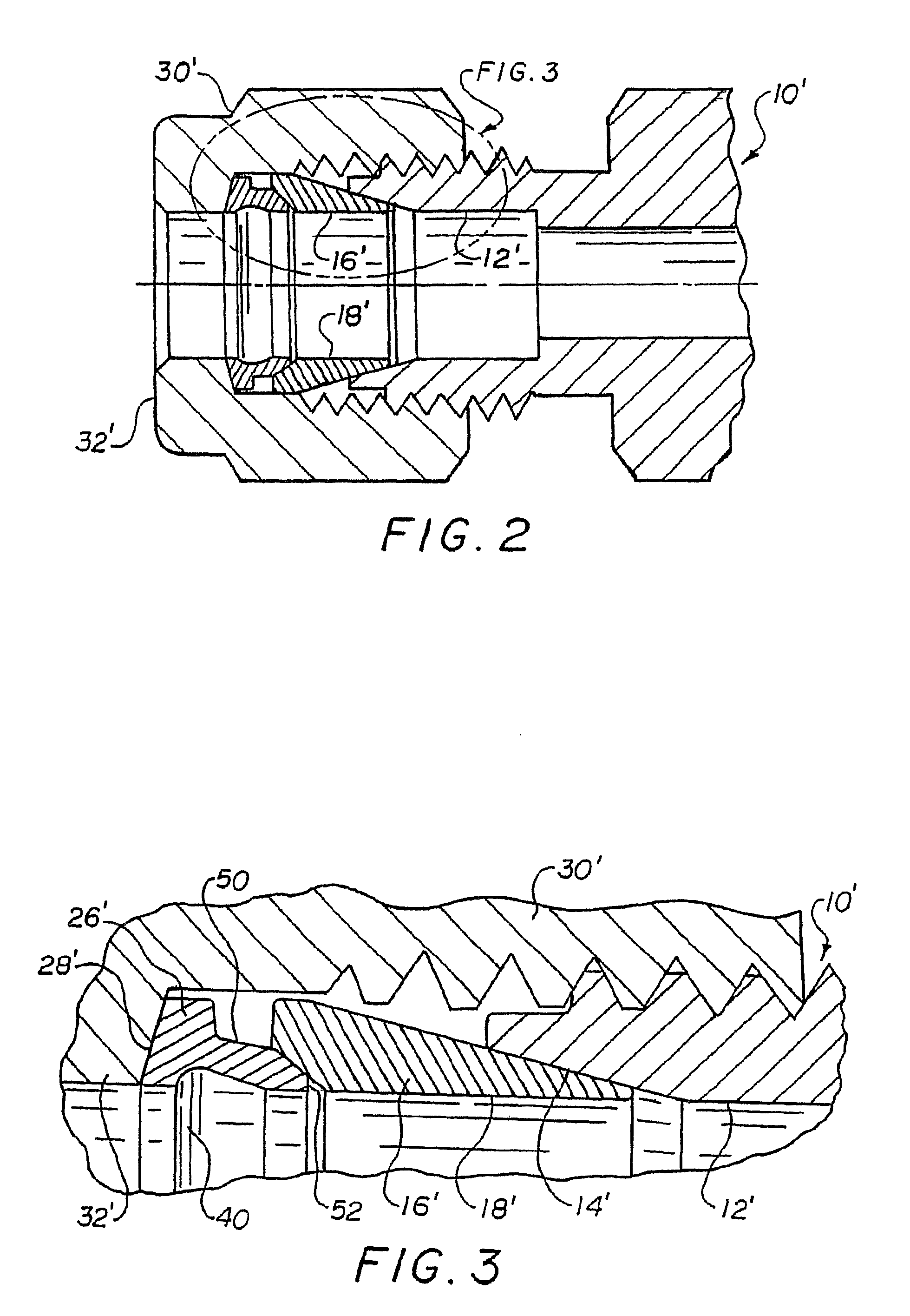
[0011]In accordance with one embodiment of the invention, a tube fitting includes a fitting body having a cylindrical bore for receiving a tube end and including a tapered mouth at one end of the bore; a drive member having a threaded engagement with the body and having a ferrule drive surface; a first ferrule having a tapered first end that extends into the tapered mouth of the fitting body and having a second end with a tapered recess that axially extends toward the first end; and a second ferrule having a cylindrical interior wall, a tapered first end that extends into the tapered recess of the first ferrule, and having a contoured face on a second end thereof that engages the drive member ferrule drive surface; the second ferrule interior wall having a circumferential recess located between the first and second ends of the second ferrule; the recess and the contoured face reducing stress concentrations on the drive member drive surface when the fitting is made up.

Problems solved by technology

The thickness of the nose portion cannot be reduced to an extent that the rear ferrule deforms too much and only the rear ferrule adequately grips the outer wall of the tubing.
On the other hand, the thickness of the nose of the rear ferrule cannot be enlarged to such an extent that it results in a structural arrangement that is too stiff and does not permit the desired rear ferrule deformation.
This also noticeably increases the nut torque forces experienced during make-up even if galling is absent.

Method used


Image

  • Ferrule with plural inner diameters
  • Ferrule with plural inner diameters
  • Ferrule with plural inner diameters

Examples


Embodiment Construction

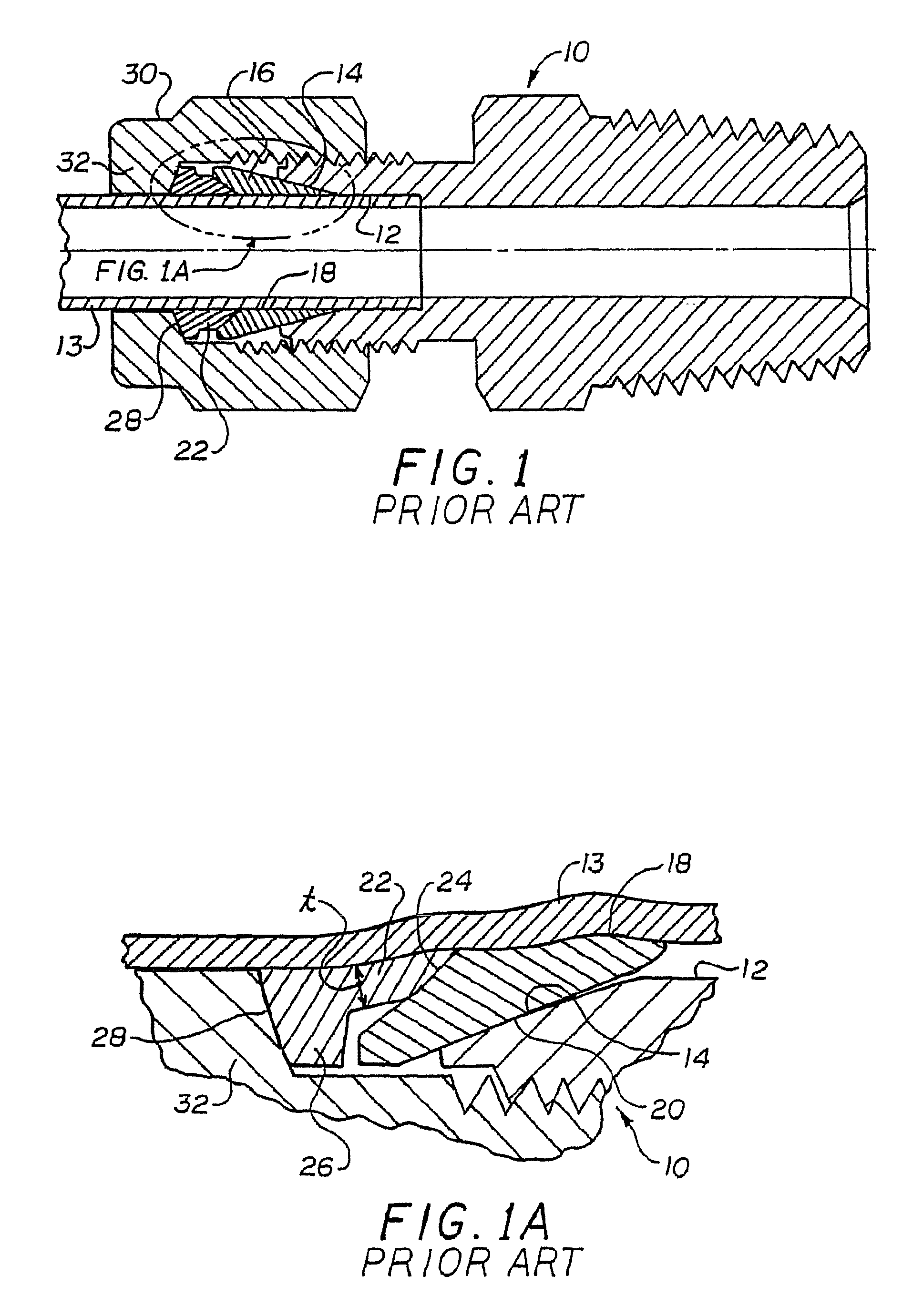
[0044]Referring now to the drawings wherein the showings are for the purposes of illustrating preferred embodiments of the invention only and not for purposes of limiting same, FIG. 2 illustrate the overall arrangement of a fitting incorporating the invention. It should be noted that in many of the illustrations herein of the ferrule profiles, the ferrules are shown in partial cross-section for clarity and ease of understanding, particularly for views of the ferrule geometry and profile wherein it is only necessary to illustrate a portion of the entire ferrule in sectional view. The FIG. 2 embodiment has the major components identified with the same reference numerals used with respect to the description of the prior art device of FIGS. 1 and 1A. A description of a FIG. 1 element is to be taken as equally applicable to the FIG. 2 elements that are correspondingly numbered unless otherwise noted. In particular, in the FIG. 2 embodiment, the rear ferrule 22′ has been modified in a man...


PUM

PropertyMeasurementUnit
stress concentrationsaaaaaaaaaa

Abstract

A ferrule for a metal tube fitting includes a body that is case hardened over substantially its entire surface. The ferrule also has an interior wall comprising first and second cylindrical portions, the first cylindrical portion being axially adjacent a front edge of the ferrule and having the smallest interior wall diameter of the ferrule, the second cylindrical portion having a larger diameter than said first cylindrical portion.

Description

RELATED APPLICATIONS[0001]This application is a continuation of U.S. patent application Ser. No. 10 / 707,697 filed on Jan. 5, 2004, for FERRULE WITH PLURAL INNER DIAMETERS, now U.S. Pat. No. 7,240,929, which is a continuation of U.S. patent application Ser. No. 10 / 374,026 filed on Feb. 25, 2003 for FERRULE WITH RELIEF TO REDUCE GALLING, which is a continuation of granted U.S. patent application Ser. No. 09 / 469,549 filed on Dec. 12, 1999 for FERRULE WITH RELIEF TO REDUCE GALLING, now U.S. Pat. No. 6,629,708 which is a continuation-in-part of U.S. patent application Ser. No. 09 / 054,186 filed on Apr. 2, 1998, now U.S. Pat. No. 6,131,963, which is a continuation-in-part of U.S. patent application Ser. No. 08 / 834,255 filed on Apr. 15, 1997, now U.S. Pat. No. 5,882,050, the entire disclosures of which are fully incorporated herein by reference.BACKGROUND OF INVENTION[0002]The subject invention is directed to the art of ferrule type tube fittings. More particularly, the invention concerns a...

Claims


Application Information

Patent Timeline
Patent Type & Authority Patents(United States)
IPC IPC(8): F16L19/06F16L19/10
CPCF16L19/10F16L19/0653F16L19/103
Inventor WILLIAMS, PETER C.KUHNS, HOWARD C. B.
Owner SWAGELOK CO
Why Eureka
Try Eureka