
Device and method for a gas burner

a gas burner and device technology, applied in the direction of gaseous heating fuel, combustion types, domestic stoves or ranges, etc., can solve the problems of inability to support, particularly troublesome manipulation of the oven door, adverse changes in the flame characteristic,

Active Publication Date: 2009-11-10
HAIER US APPLIANCE SOLUTIONS INC
View PDF27 Cites 26 Cited by
  • Summary
  • Abstract
  • Description
  • Claims
  • Application Information

AI Technical Summary

Benefits of technology

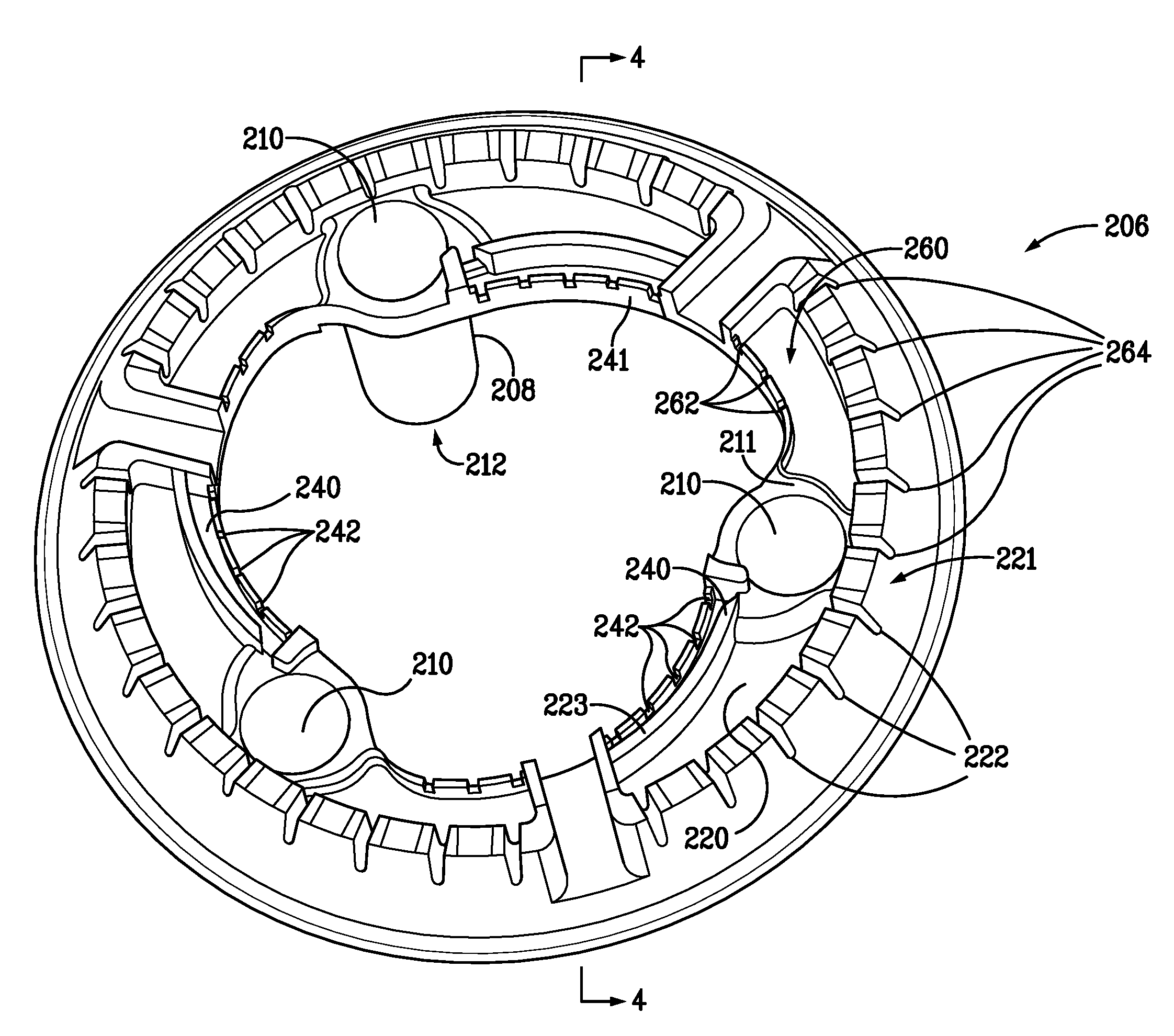
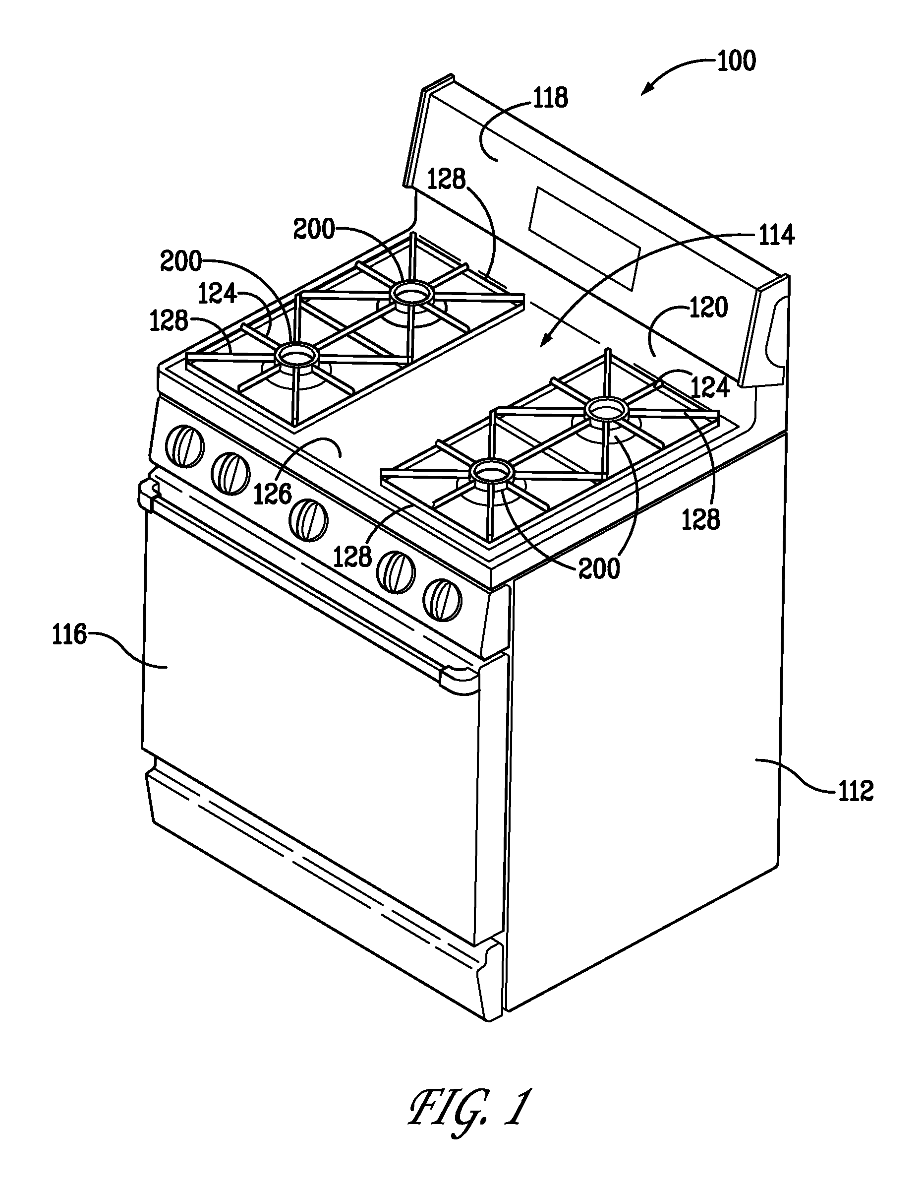
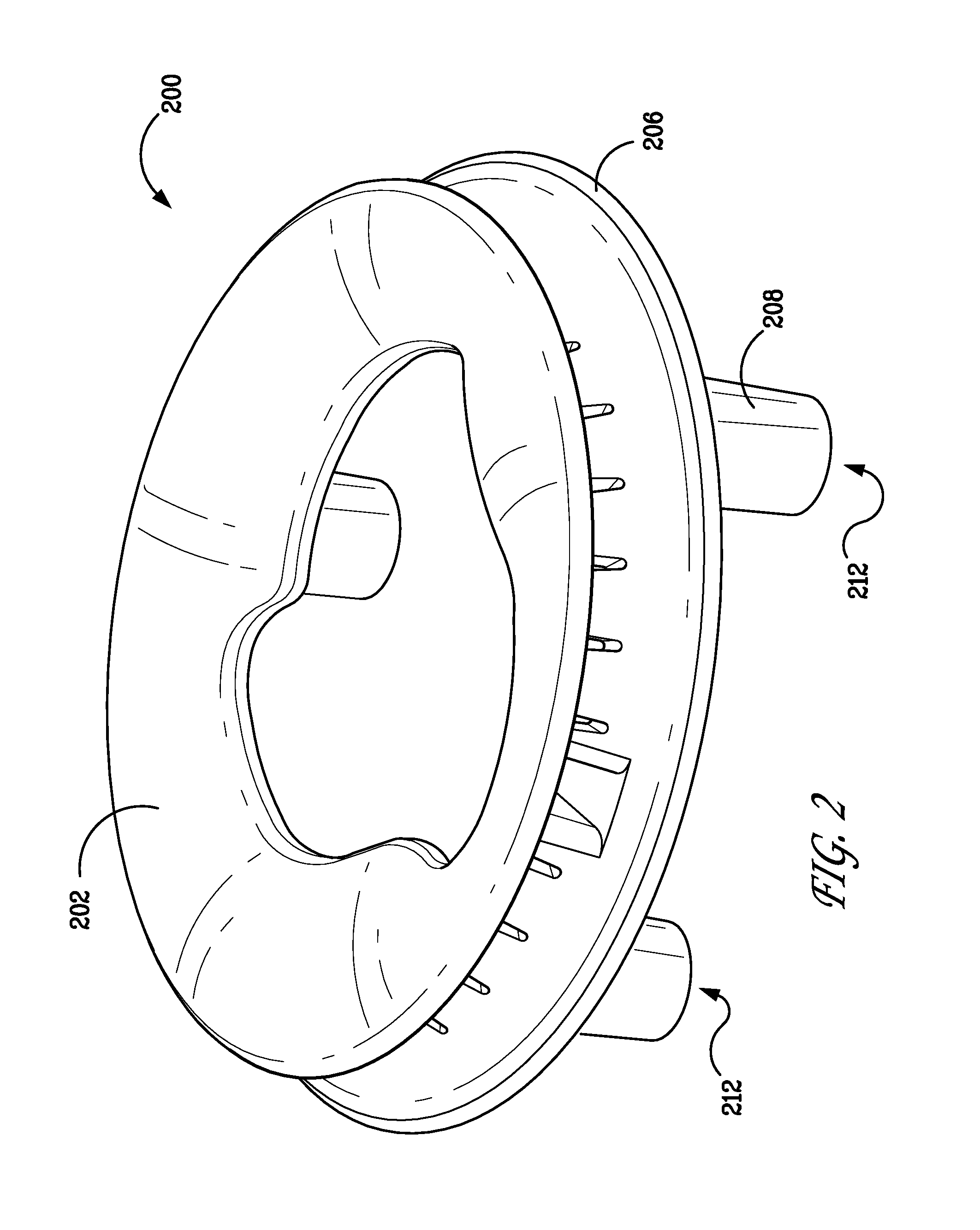
The invention is a gas range with a cook top and gas burner assembly that can adjust the output of gas based on the flow rate of the gas. The burner assembly has two chambers with different ports for gas distribution. The first chamber has a tripping pin to control the gas flow during high or low flow conditions. The method also includes a projection that allows for uniform gas distribution during low input rates and limits the gas distribution to the second chamber during high input rates. The burner body has two gas inputs, each in a separate chamber with a port for gas distribution. The technical effects of the invention include improved gas control and efficiency for cooking at different gas input rates.

Problems solved by technology

Manipulation of the oven door is particularly troublesome because rapid openings and closings of the oven door often produce respective under-pressure and over-pressure conditions under the cook top.
Adverse changes in the flame characteristic are detrimental to various performance characteristics such as inability to support flames at certain ports particularly at very low gas input rates.
For example, where the port designs are optimized for low flow, the ports produce poor and undesirable operational conditions during high flow.

Method used


Image

  • Device and method for a gas burner
  • Device and method for a gas burner
  • Device and method for a gas burner

Examples


Embodiment Construction

[0017]While the methods and apparatus are herein described in the context of a gas-fired cook top, as set forth more fully below, it is contemplated that the herein described method and apparatus may find utility in other applications, including, but not limited to, gas heater devices, gas ovens, gas kilns, gas-fired meat smoker devices, and gas barbecues. In addition, the principles and teachings set forth herein may find equal applicability to combustion burners for a variety of combustible fuels. The description herein below is therefore set forth only by way of illustration rather than limitation, and is not intended to limit the practice of the herein described methods and apparatus.

[0018]Typically, for a burner chamber, flow distribution is governed by individual port areas. The larger port exhibits higher flow rates than smaller ports. Thus, port sizing, a static attribute of a burner, primarily determines this flow characteristic. This defines the distribution of flow rates ...


PUM


Abstract

A gas range having a cook top and a gas burner assembly connected to a source of gas having a variable flow rate. The burner assembly is positioned in the cook top. The gas burner assembly has a burner body with a gas input, the gas input is in a first flow communication with a first chamber and a second flow communication with a second chamber. Each chamber has at least one port in an exterior wall for flow communication to an area external of the burner body for combustion of the gas. The second flow communication has a tripping pin to deflect flow during high flow conditions and to not deflect flow during low flow conditions. A burner cap is positioned on the burner body.

Description

BACKGROUND OF THE INVENTION[0001]This invention relates generally to a method and apparatus for gas burners, and, more particularly, a method and apparatus for improved flow characteristics for gas surface burners used in a gas-cooking product.[0002]Atmospheric gas burners are commonly used as surface units in household gas cooking appliances. A significant factor in the performance of gas burners is their ability to withstand airflow disturbances from the surroundings, such as room drafts, rapid movement of cabinet doors, and oven door manipulation. Manipulation of the oven door is particularly troublesome because rapid openings and closings of the oven door often produce respective under-pressure and over-pressure conditions under the cook top.[0003]Gas surface burners used in cooking products typically include a burner body including a plurality of burner ports through which a gas is distributed, and a burner cap positioned over the burner body. Almost all designs include an inte...

Claims


Application Information

Patent Timeline
Patent Type & Authority Patents(United States)
IPC IPC(8): F23C9/00
CPCF23D14/06F23D2900/14064F23D2900/14063F23D2900/14062
Inventor MCCROREY, PAUL E.CADIMA, PAUL BRYANKUMAR, SHREE
Owner HAIER US APPLIANCE SOLUTIONS INC
Learn More