
Multiple generator loadcenter and method of distributing power from multiple generators

a generator and loadcenter technology, applied in the field of loadcenters, can solve the problems of increasing the cost and complexity of operating and maintaining a larger generator in comparison, requiring relatively large quantities of maintenance fluid, and presenting various disadvantages of relatively larger electric generators

Inactive Publication Date: 2009-11-10
EATON CORP
View PDF18 Cites 24 Cited by
  • Summary
  • Abstract
  • Description
  • Claims
  • Application Information

AI Technical Summary

Benefits of technology

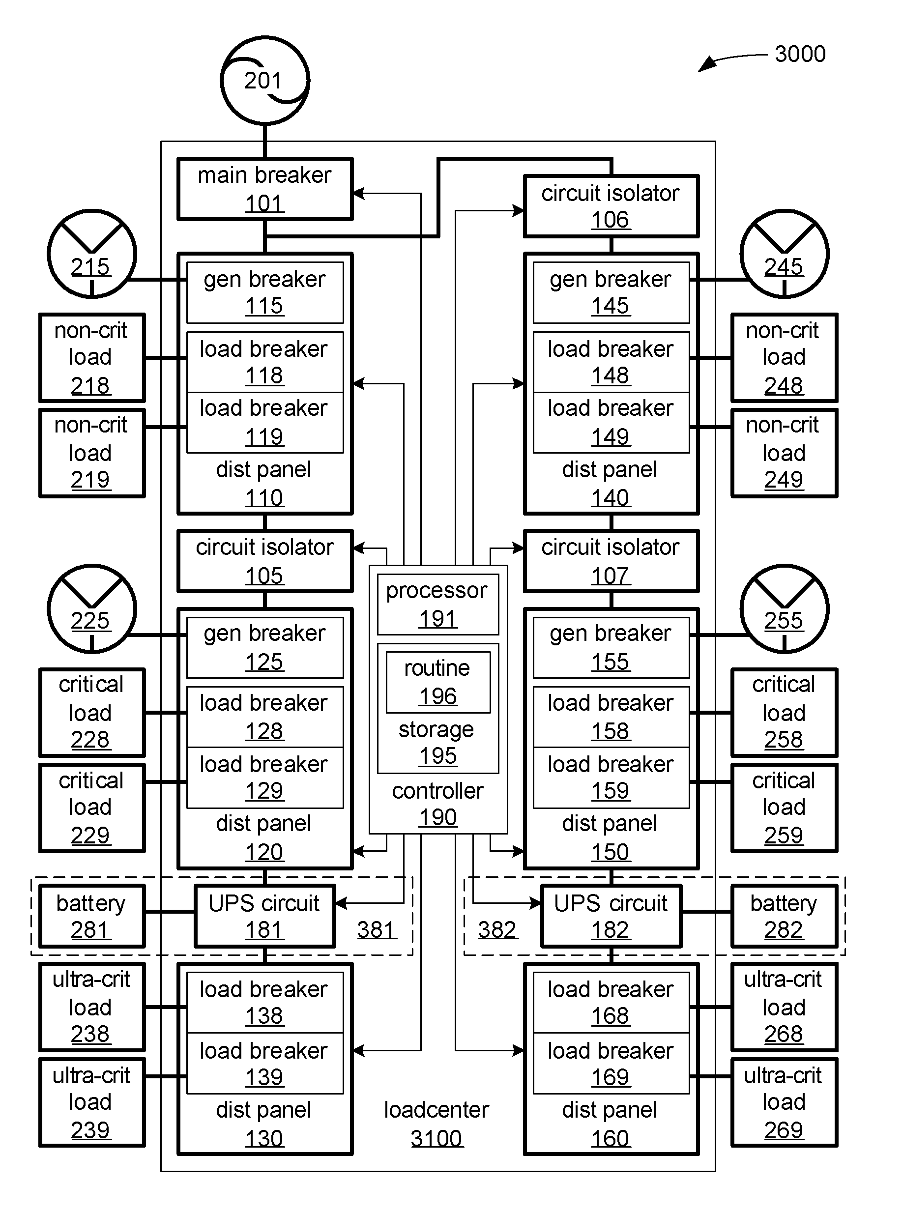
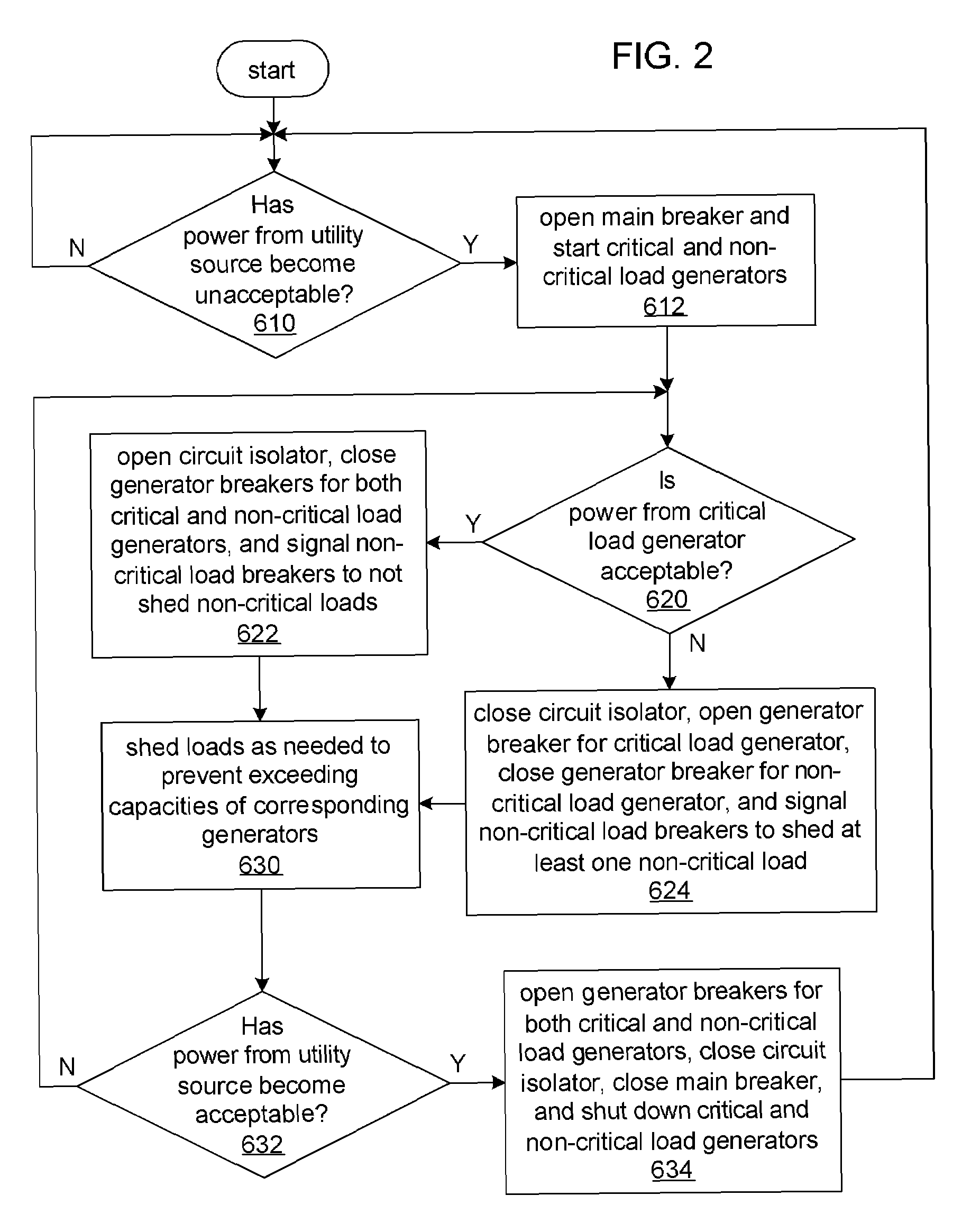
The invention provides a loadcenter that can isolate two or more distribution panels to accommodate critical and non-critical loads being supplied with power from separate generators. The loadcenter also includes a circuit isolator to selectively supply power from one distribution panel to another. The loadcenter can monitor the status of the power sources and quickly switch between them based on their availability. This ensures that the critical load is always supplied with power, even if one of the generators fails. The technical effect of this invention is to provide a reliable and flexible power distribution system that can quickly switch between different power sources to ensure a steady supply of power to critical loads.

Problems solved by technology

Unfortunately, relatively larger electric generators present various disadvantages over relatively smaller electric generators.
While smaller electric generators are typically air cooled, larger electric generators typically require a liquid cooling system with a circulation pump and radiator, thereby adding to both the costs and complexities of operating and maintaining a larger generator in comparison to a smaller generator.
Larger generators also require relatively larger quantities of maintenance fluids, including lubrication oil and coolant liquid.
However, combining the output of multiple generators is hampered by the AC outputs of independent generators often being out of phase.
Known techniques for combining such unsynchronized supplies of power into a single supply of power with acceptable alternating current (AC) characteristics are both cumbersome and expensive.
Unfortunately, typical commercially available uninterruptible power supplies are standalone device that are typically placed directly in rooms where they are needed, and are not designed to coordinate their operation of providing uninterrupted power to ultra-critical loads with the operation of electric generators to most efficiently ensure the provision of electric power to different loads of differing priority.

Method used


Image

  • Multiple generator loadcenter and method of distributing power from multiple generators
  • Multiple generator loadcenter and method of distributing power from multiple generators
  • Multiple generator loadcenter and method of distributing power from multiple generators

Examples


Embodiment Construction

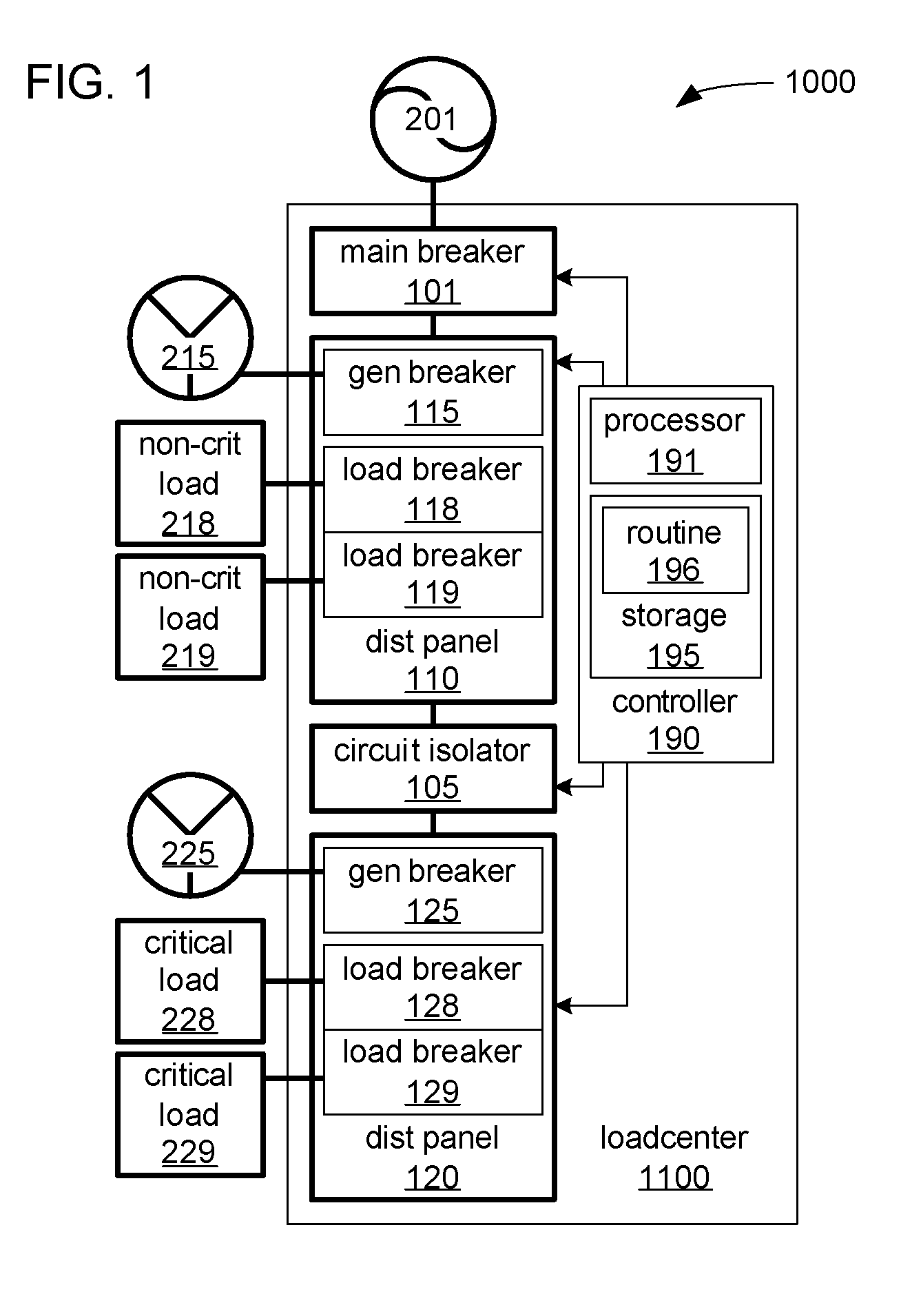
[0019]Referring to FIG. 1, a loadcenter installation 1000 to selectively provide electrical power to non-critical and critical loads (e.g., non-critical loads 218-219 and critical loads 228-229 depicted in FIG. 1) from multiple alternate sources incorporates generator power sources 215 and 225, and a loadcenter 1100 distributing electric power, at various times, from one or both of the generator power sources 215 and 225, or from a utility power source (e.g., utility power source 201 depicted in FIG. 1) to one or more non-critical and critical loads. As will be explained, the loadcenter 1100 normally distributes power received from the utility power source 201, unless the utility power source 201 becomes unacceptable, in which case, the loadcenter 1100 distributes power from one or both of the generator power sources 215 and 225. The non-critical loads 218-219 and the critical loads 228-229 represent one or more electrical devices within, for example, a commercial or residential str...


PUM


Abstract

A loadcenter for supplying power to a critical load is capable of isolating a distribution panel distributing power to the critical load from another distribution panel distributing power to a non-critical load to enable the isolated distribution panels being supplied with power from separate generator power sources in response to power supplied by a utility power source to both distribution panels becoming unacceptable.

Description

CROSS-REFERENCE TO RELATED APPLICATION[0001]This application is related to commonly assigned, concurrently filed: U.S. patent application Ser. No. 11 / 738,832, filed Apr. 23, 2007, entitled “Multiple Generator Loadcenter and Method of Distributing Power from Multiple Generators”.BACKGROUND OF THE INVENTION[0002]1. Field of the Invention[0003]This invention pertains generally to loadcenters and, more particularly, to loadcenters accommodating critical loads and non-critical loads being supplied with power from separate generators in response to power from a utility service becoming unacceptable. This invention also relates to methods of distributing power from separate generators to critical loads and non-critical loads.[0004]2. Background Information[0005]Loadcenters incorporating a multitude of circuit breakers to provide a safe and controllable distribution of electrical power have become a common feature in both residential and commercial structures. Increasingly, such loadcenters...

Claims


Application Information

Patent Timeline
Patent Type & Authority Patents(United States)
IPC IPC(8): H02J9/00
CPCH02J3/14H02J9/06Y04S20/248Y02B70/3291Y04S20/222Y02B70/3225Y02B70/30H02J2310/60
Inventor LATHROP, TODD M.WEHRLI, JONATHAN A.
Owner EATON CORP
Learn More