
Double frangible bearing support

a bearing support and double-fangible technology, applied in the direction of bearing unit rigid support, machines/engines, mechanical equipment, etc., can solve the problems of significant imbalance, and affecting the operation of the engin

Active Publication Date: 2015-06-25
PRATT & WHITNEY CANADA CORP
View PDF3 Cites 20 Cited by
  • Summary
  • Abstract
  • Description
  • Claims
  • Application Information

AI Technical Summary

Benefits of technology

This patent describes a gas turbine engine with a rotor and multiple bearing assemblies for supporting the rotor. The first bearing assembly has a conical support structure, with a second assembly having rolling elements between inner and outer races. The second assembly also has frangible bolts connecting it to the support structure. This design ensures that if there are critical loads due to rotor imbalances or radial displacements, the bearing assemblies will fail in a safe and controlled manner. The technical effect of this patent is to improve the reliability and safety of gas turbine engines.

Problems solved by technology

However, in certain circumstances, a fan may be damaged to such an extent that parts of one or more of the fan blades become detached from the rotor disk (referred to herein as a fan blade off event or FBO event).
This may result in a significant imbalance requiring shutdown of the engine to minimise load transmission to the aircraft.
The imbalance in the fan created by the blade loss generates extremely high radial loads which must at least be partially absorbed as the engine is run down to windmilling speed (i.e. the speed at which the rotor spins in a non-operative condition as a result of the aircraft moving through the air).
Under certain circumstances, the vibration resulting from the fan imbalance at windmilling speed can still be considerable.
If not appropriately controlled, these vibrations may damage the engine structure and the aircraft and present difficulties to control the aircraft during approach.

Method used


Image

  • Double frangible bearing support
  • Double frangible bearing support
  • Double frangible bearing support

Examples


Embodiment Construction

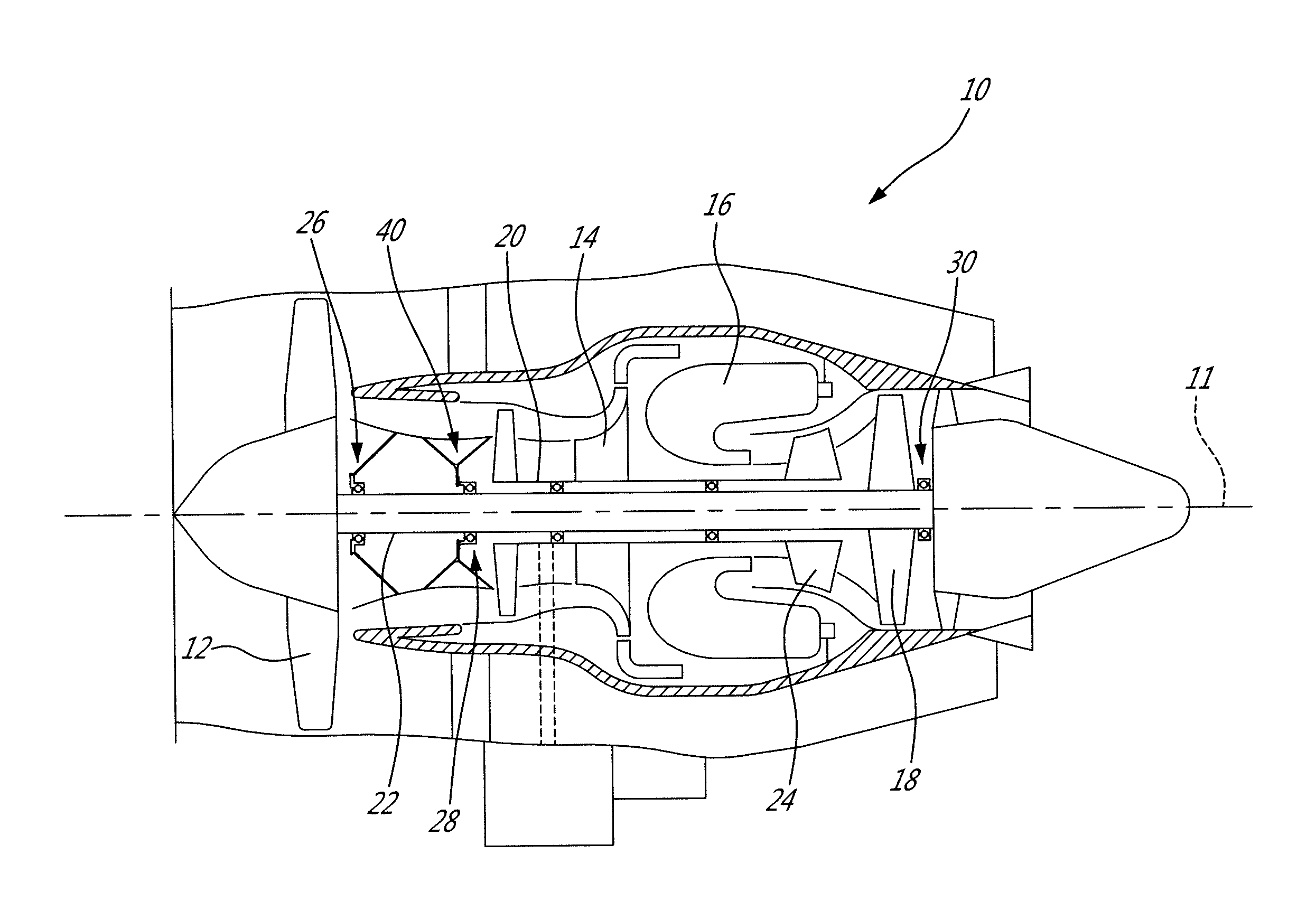
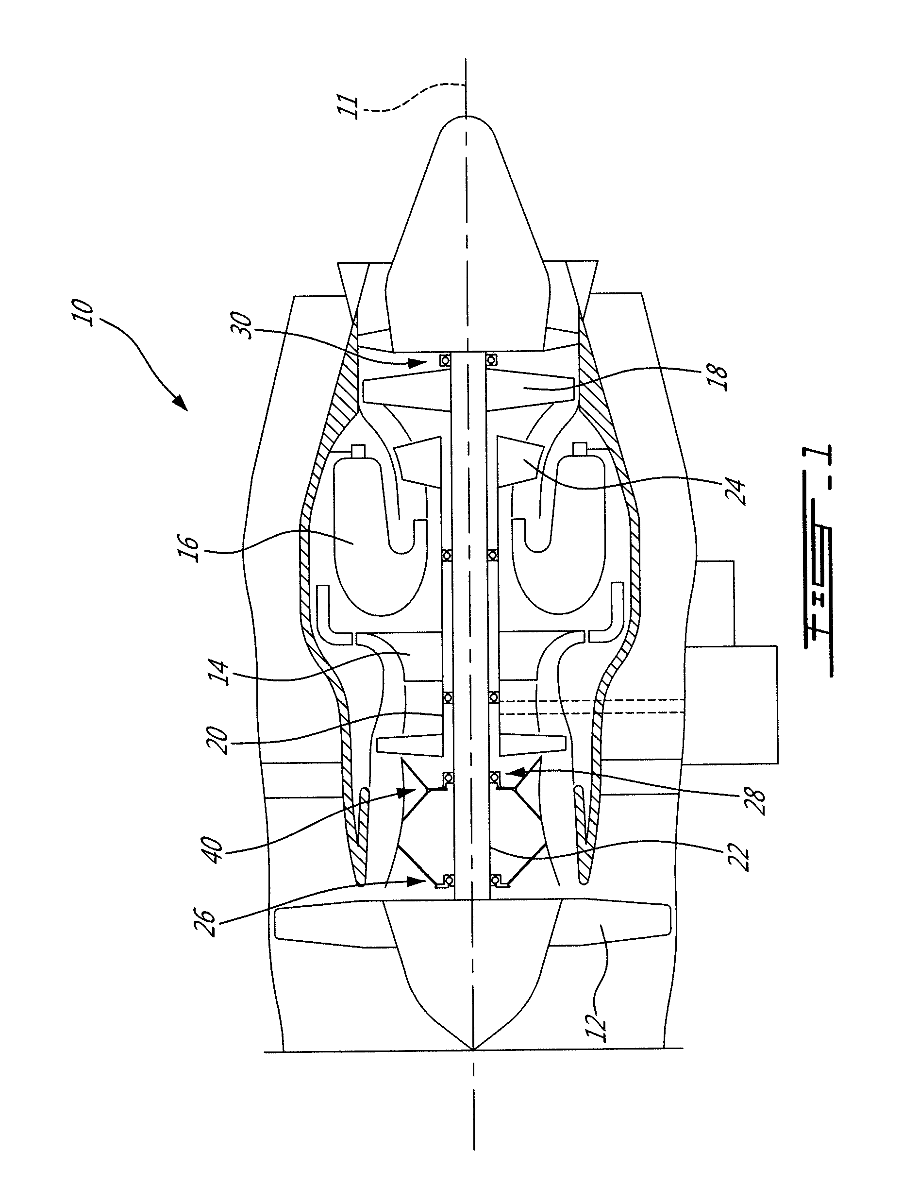
[0011]FIG. 1 illustrates a turbofan gas turbine engine 10 of a type preferably provided for use in subsonic flight and generally comprising a low pressure spool assembly, which includes a fan assembly 12, a low pressure compressor assembly (not shown) and a low pressure turbine assembly 18 connected by a low pressure shaft 22, and a high pressure spool assembly, which includes a high pressure compressor assembly 14 and a high pressure turbine assembly 24 connected by a high pressure shaft 20. The engine 10 further comprises a combustor 16 in which compressed air from the high pressure compressor 14 is mixed with fuel and ignited for generating an annular stream of hot combustion gases from which the low pressure and high pressure turbine sections extract energy, as known in the art.

[0012]The low pressure spool is rotatably supported by a number of axially spaced-apart bearings concentrically mounted about the central axis 11 of the engine 10. The low pressure shaft 22 is supported a...


PUM


Abstract

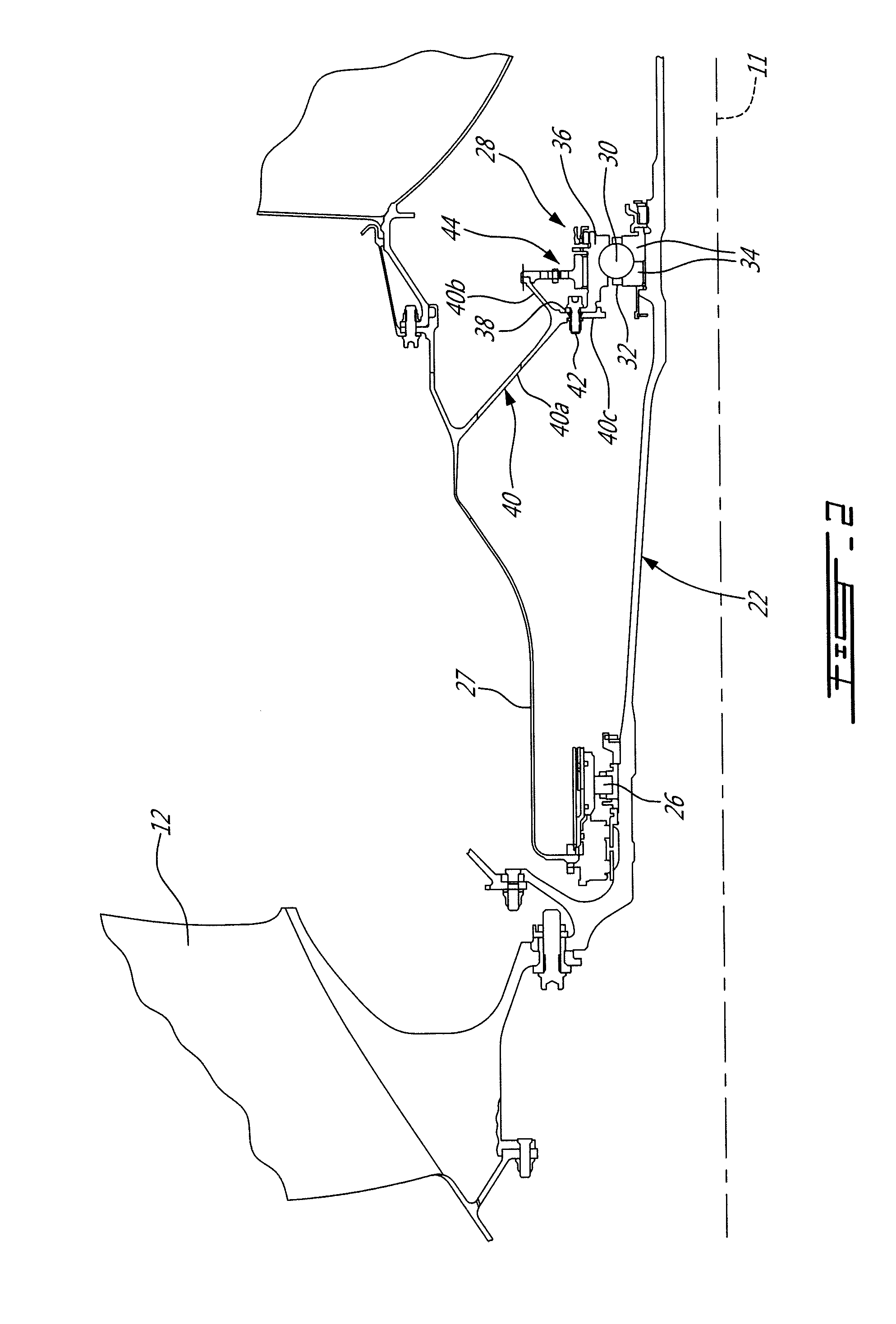
A double frangible bearing support structure supports a low pressure rotor of an aircraft engine. The support structure has a first bearing assembly including a first bearing supported by a first bearing support adapted to buckle or frange when subject to a predetermined critical load resulting from an abnormal rotor imbalance. The support structure has a second bearing assembly comprising a second bearing having rolling elements disposed between inner and outer races. The outer race is connected to a second bearing support by means of frangible bolts adapted to fail when subject to a predetermined critical load resulting from radial displacements and loads of the low pressure rotor following decoupling / franging at the first bearing support.

Description

TECHNICAL FIELD[0001]The application relates generally to aircraft engines and, more particularly, to a bearing support arrangement for a spinning rotor in an aircraft engine.BACKGROUND OF THE ART[0002]The fans of aircraft engines are designed to resist damage caused by foreign object ingestion. However, in certain circumstances, a fan may be damaged to such an extent that parts of one or more of the fan blades become detached from the rotor disk (referred to herein as a fan blade off event or FBO event). This may result in a significant imbalance requiring shutdown of the engine to minimise load transmission to the aircraft. The imbalance in the fan created by the blade loss generates extremely high radial loads which must at least be partially absorbed as the engine is run down to windmilling speed (i.e. the speed at which the rotor spins in a non-operative condition as a result of the aircraft moving through the air).[0003]Under certain circumstances, the vibration resulting from...

Claims


Application Information

Patent Timeline
IPC IPC(8): F01D25/16F01D21/14F16C35/04
CPCF01D25/162F16C35/04F05D2240/54F05D2240/52F01D21/14F05D2250/232F16C2360/23F16C35/067F16C19/52F16C33/586Y02T50/60
Inventor RAYKOWSKI, LENASMAILYS, HARVEYBEAMISH, DAVE
Owner PRATT & WHITNEY CANADA CORP
Learn More