Method and apparatus for transfer of a critical load from one source to a back up source using magnetically latched relays

a technology of critical load and magnetic latching, which is applied in the direction of relays, emergency power supply arrangements, transportation and packaging, etc., can solve the problems of reducing the reliability of the transfer switch device, and increasing the risk of critical load dropping. , to achieve the effect of reducing contact boun

Active Publication Date: 2008-03-06
TWINSOURCE POWER SYST INC
View PDF9 Cites 20 Cited by
  • Summary
  • Abstract
  • Description
  • Claims
  • Application Information

AI Technical Summary

Benefits of technology

[0010] In accordance with a first aspect of the present invention, an automatic transfer switch includes a first voltage input adapted for connection to a first associated voltage source and a second voltage input adapted for connection to a second associated voltage source. A first magnetically latched relay has an opened state and a closed state, wherein the first magnetically latched relay is magnetically latched in either its opened or closed state by a permanent magnet and without a holding current supplied to the first magnetically latched relay. A second magnetically latched relay has an opened state and a closed state, wherein the second magnetically latched relay is magnetically latched either its opened or closed state by a permanent magnet and without a holding current supplied to the second magnetically latched relay. The second magnetically latched relay is in its opened state when the first magnetically latched relay is in its closed state, and the second magnetically latched relay is in its closed state when the first magnetically latched relay is in its opened state. First and second voltage outputs are adapted for connection to an associated load. The first voltage output is selectively connected to the first voltage input via the first magnetically latched relay when the first magnetically latched relay is in its closed state, and the second voltage output selectively connected to the second voltage input via the second magnetically latched relay when the second magnetically latched relay is in its closed state. A voltage sensing and control logic circuit monitors the first and second voltage inputs and selectively and temporarily energizes the first and second magnetically latched relays, wherein one of the first and second magnetically latched relays changes from its opened state to its closed state and the other of said first and second magnetically latched relays changes from its closed state to its opened state when the first and second magneticall

Problems solved by technology

There are two serious technical issues however associated with the use of standard relays that are either detrimental to the relay's longevity (thus reducing the reliability of the transfer switch device) or produce multiples of on-off voltage waveforms that are not acceptable to some of the more sensitive electronic loads (thus increasing the risk of dropping the critical loads).
A cross connection would create a cross current between an already failed primary source S1 and the good alternate source S2, thus causing the alternate source to fail as well and drop the critical load.
This is intended by design because it has been well established that statistically the number one cause of failure in relays is the failure of the relay coil (it can either short or open and in both situations the relay is rendered non-functional and can no longer transfer—i.e., a standard relay with a failed coil will return to or remain in its default state under force of the relay biasing spring).
The primary cause of relay

Method used


Image

  • Method and apparatus for transfer of a critical load from one source to a back up source using magnetically latched relays
  • Method and apparatus for transfer of a critical load from one source to a back up source using magnetically latched relays
  • Method and apparatus for transfer of a critical load from one source to a back up source using magnetically latched relays

Examples


Embodiment Construction

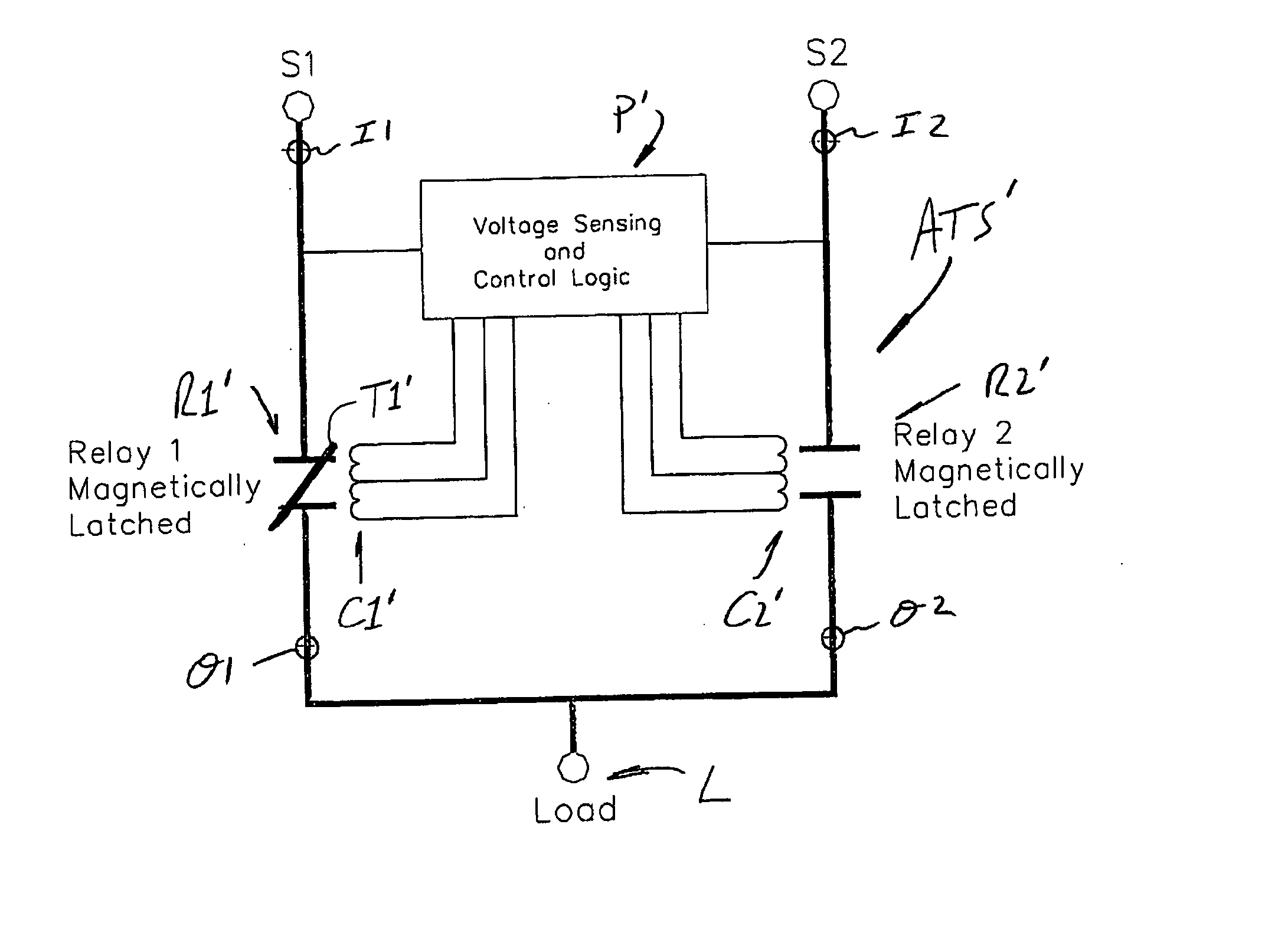
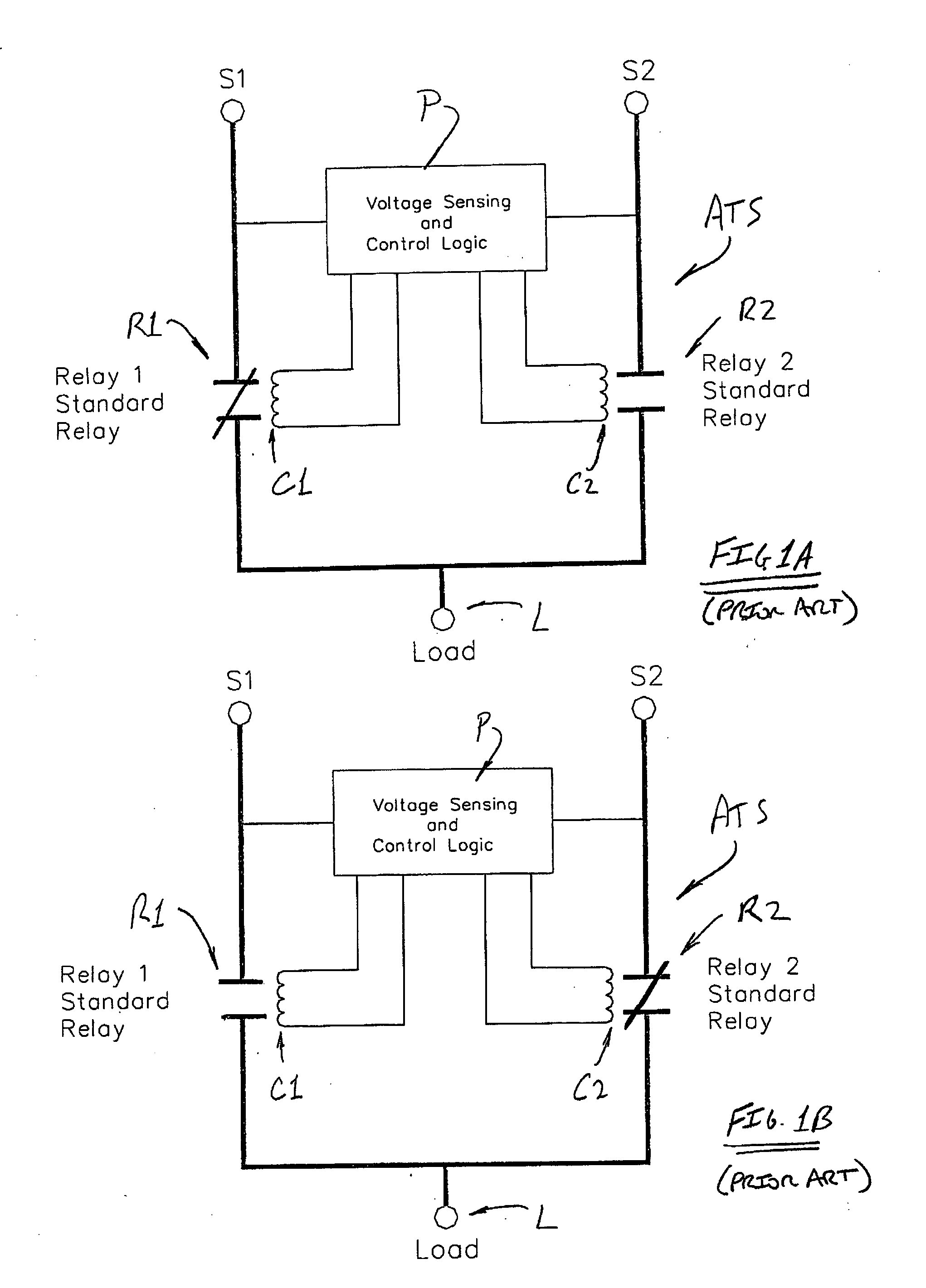
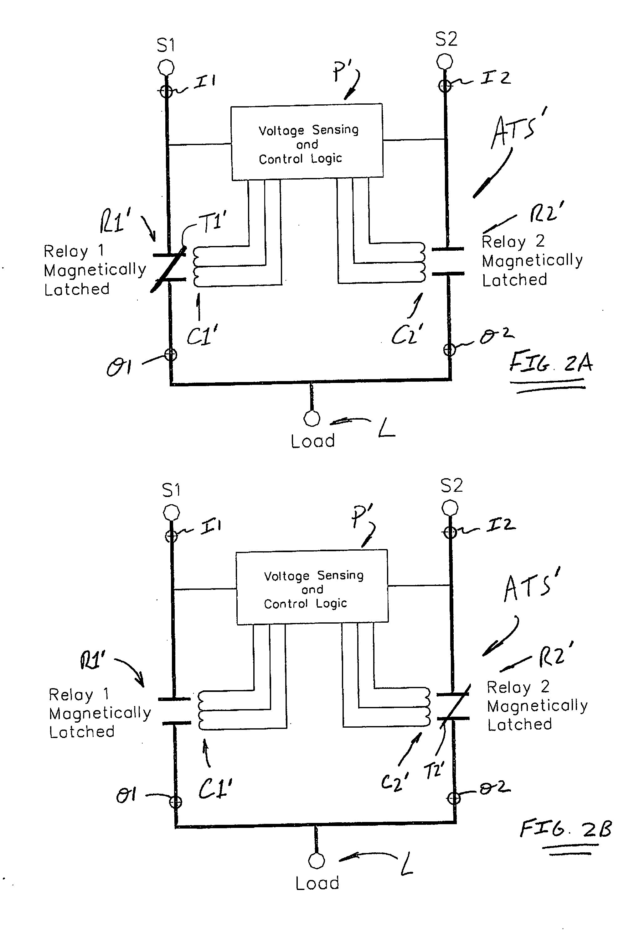
[0016] The present invention makes use of magnetically latched relays to yield a much higher reliability automatic transfer switch product by eliminating the continuously energized state of the relays while the switch is connected to the alternate source. As used herein, the term “magnetically latched relay” is intended to encompass a relay having contacts that hold in both the opened and closed states by means of a magnet, e.g., a permanent magnet, without requiring the relay coil to be energized continuously to hold the relay contacts in either state. In a magnetically latched relay, as that term is used herein, the relay coil must be energized to move the contacts from the opened to the closed state and from the closed to the opened state, after which change-of-state, the coil is de-energized without causing any change-of-state of the relay contacts which are held in place by a magnet of the relay, i.e., the relay coil must be energized to move the relay contacts, but not to hold...


PUM


Abstract

An automatic transfer switch includes first and second magnetically latched relays that respectively connect first and second voltage sources to a critical load. The first and second relays are magnetically latched in their respective opened or closed positions by a permanent magnet so that no holding current is supplied to the relays after switching is completed. As such, no holding current is required for either relay in the non-transferred or the transferred state of the automatic transfer switch, which reduces heat generated by the relays which can lead to relay failure. A switching method uses the automatic transfer switch to switch voltage sources without requiring relay holding currents in either the non-transferred or transferred state. A method of reducing contact bounce is also disclosed.

Description

CROSS-REFERENCE TO RELATED APPLICATION [0001] This application claims priority from and benefit of the filing date of U.S. provisional patent application Ser. No. 60 / 747,484 filed May 17, 2006 (May 17, 2006), which is hereby expressly incorporated by reference into the present specification.BACKGROUND OF THE INVENTION [0002] Automatic Transfer Switches used to transfer a critical electronic load from a preferred source to an alternate source that utilize standard relays have been in use for some time. There are two serious technical issues however associated with the use of standard relays that are either detrimental to the relay's longevity (thus reducing the reliability of the transfer switch device) or produce multiples of on-off voltage waveforms that are not acceptable to some of the more sensitive electronic loads (thus increasing the risk of dropping the critical loads). [0003] The present invention makes use of a particular type of relay in an automatic transfer switch that ...

Claims


Application Information

Patent Timeline
IPC IPC(8): H02J9/06
CPCH01H9/26H02J9/061H01H2300/018H01H51/01
Inventor PHELPS, DAVID R.TAMJIDI, FRED
Owner TWINSOURCE POWER SYST INC
Why Eureka
Try Eureka