Instrument panel rib structure

a technology of supporting structure and instrument panel, which is applied in the direction of monocoque structure, analog and hybrid computing, superstructure subunits, etc., can solve the problems of prohibitively heavy structure, prohibitive weight of clamping machine, and inability to be installed into a vehicl

Inactive Publication Date: 2006-12-21
SIMONDS GLEN +1
View PDF8 Cites 20 Cited by
  • Summary
  • Abstract
  • Description
  • Claims
  • Application Information

AI Technical Summary

Benefits of technology

[0007] A method of designing an instrument panel support structure using a computer aided engineering platform is provided commencing with the steps of inputting the positioning coordinates of selected fixing and mounting surfaces for an instrument panel support structure and inputting the performance requirements for stiffness and crashworthiness of the instrument panel support structure. The next step is linking the fixing and mounting surfaces together wi

Problems solved by technology

The larger the surface area, the higher clamp tonnage the die casting machine needs to keep the die halves closed while the molten metal is shot into the cast tool.
It may be possible t

Method used


Image

  • Instrument panel rib structure
  • Instrument panel rib structure
  • Instrument panel rib structure

Examples


example 1

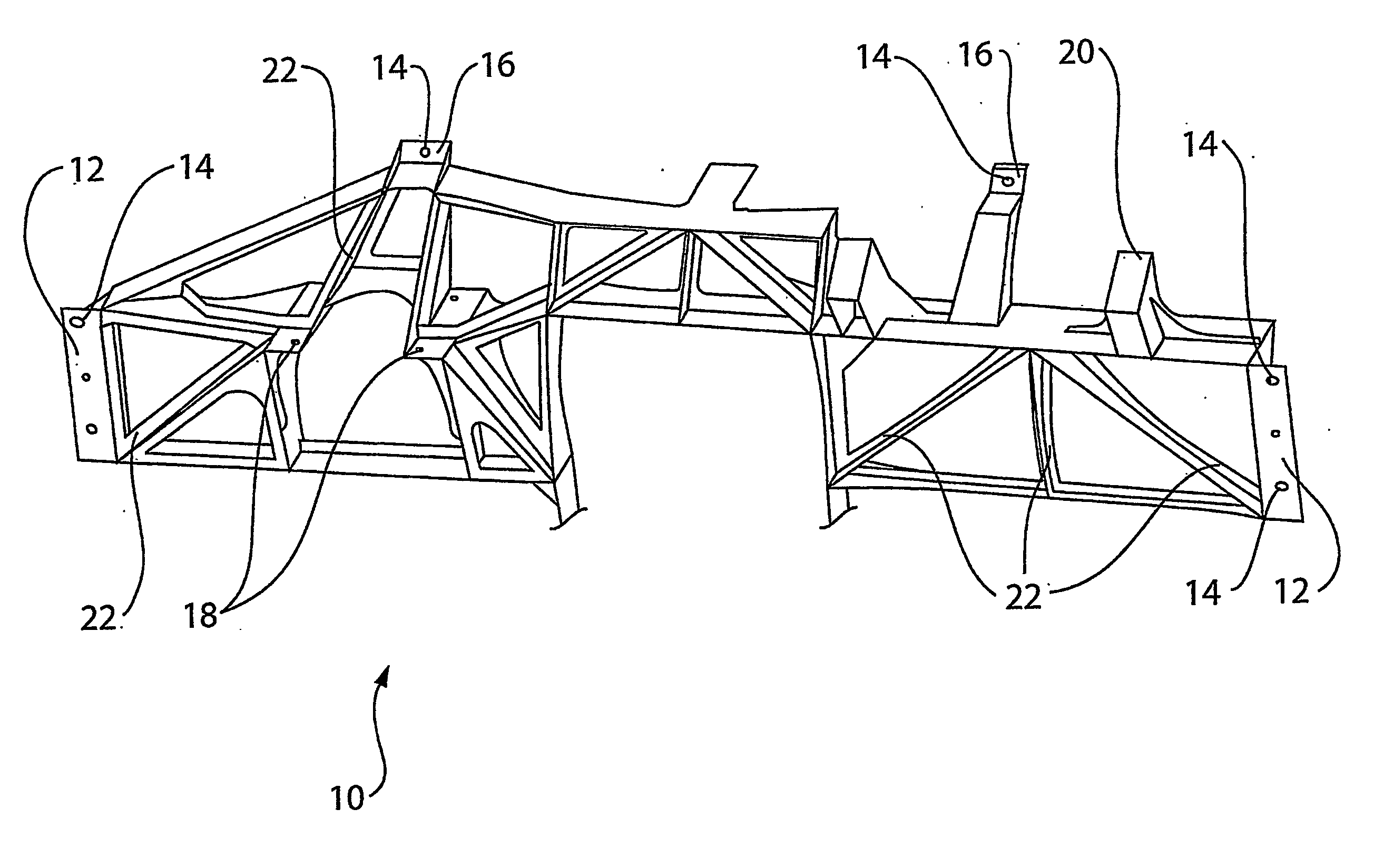
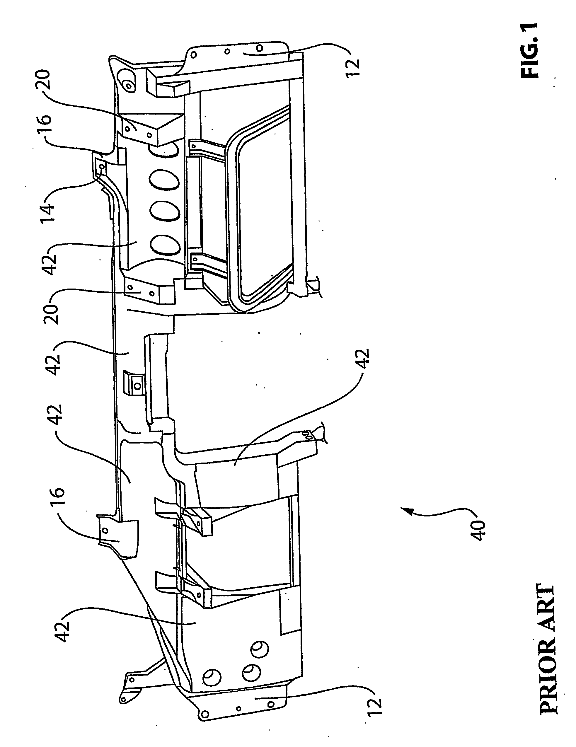
[0033] A first example of the IP support structure is illustrated in FIG. 1-FIG. 4 of the drawings. FIG. 1 shows a conventional prior art instrument panel support structure 40 constructed from cast magnesium. The conventional IP support structure has fixing surfaces 12 for attachment of the IP support structure 10 to the A pillars. Fixing surfaces 16 are positioned on the IP support structure for fixing to the screen rail so as to secure the IP support structure 10 to the vehicle frame rearward of the firewall. The IP support structure also has fixing surfaces 18 to connect it to the tunnel which houses the steering column. The conventional IP support structure has mounting surfaces 20 to which vehicle components may be attached. The conventional IP support structure 40 has a projected area of 330,000 mm2 and weighs 5.1 kg. Much of the weight and projected area are the results of the large areas of panel facing 42.

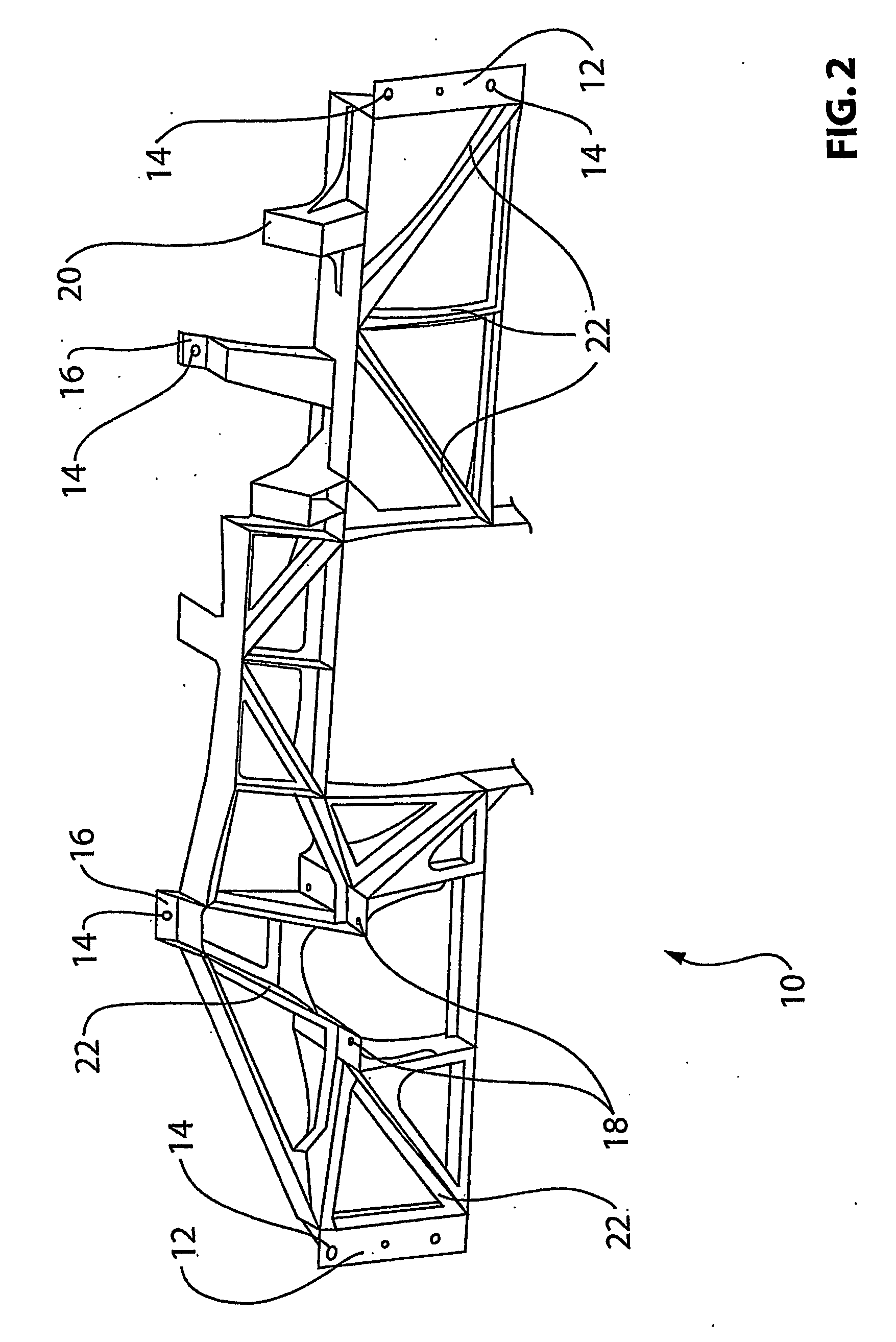
[0034] The instrument panel support structure 10 shown in FIG. 2 is ...

example 2

[0038] The second example is illustrated in FIG. 5 through FIG. 7. FIG. 5 shows a conventional prior art instrument panel support structure 50 constructed from cast magnesium. The conventional IP support structure has fixing surfaces for attachment to the vehicle frame and mounting surfaces to which vehicle components may be attached. The conventional IP support structure 50 has a projected area of 330,000 mm2 and weighs 13.0 lbs. Much of the weight and projected area are the results of the large areas of panel facing.

[0039] The instrument panel support structure 60 shown in FIG. 6 is constructed according to the present invention. The resulting structure has the fixing surfaces and the mounting surfaces at the same relative positions for attachment to the vehicle frame and for mounting of components, but the excess magnesium panel facings are not present. All extraneous material has been eliminated, leaving only ribs in an open space frame structure which connect the various fixin...


PUM


Abstract

A vehicle instrument panel support structure is provided having fixing and mounting surfaces linked together by ribs in an open space frame structure. The ribs are sized, shaped and positioned to create critical load paths and eliminate the outer skin of the instrument panel support structure. Magnesium alloy material is only placed where it is needed for structure and function. The functionality of the vehicle instrument panel support structure is maintained as are the stiffness and crashworthiness when compared to the traditional design, but the weight of the instrument panel structure and the projected area are reduced. A method of designing an instrument panel support structure using a computer aided engineering platform is also provided.

Description

FIELD OF THE INVENTION [0001] The invention relates to the design of an instrument panel support structure to be produced as a high pressure die cast magnesium part. BACKGROUND [0002] An instrument panel (IP) support structure spans from driver's side to passenger side, rearward of the firewall or front of dash. It is fixed to the vehicle body at the A pillars and screen rail. It is also attached to the steering column tunnel via interim stamped steel brackets. The key function of the IP support structure is to fix to the vehicle body structure and support, mount, locate and / or secure key components such as steering column, passenger airbag, wiring harness, electrical modules, electronics, ducting, and dashboard fascia and trim. [0003] A conventional die cast magnesium instrument panel support structure (FIG. 1) uses large flat surfaces or skin to support the internal ribbing structure developed to achieve the stiffness and crashworthiness performance. These large flat surfaces add ...

Claims


Application Information

Patent Timeline
IPC IPC(8): B62D25/14G06G7/48
CPCB62D25/145
Inventor SIMONDS, GLENSANAKNAKI, HUSSEIN
Owner SIMONDS GLEN
Why Eureka
Try Eureka