Fire control mechanism for a firearm

a control mechanism and firearm technology, applied in the field of semiautomatic pistols or handguns, can solve the problem of handguns being rendered inoperable without a magazine, and achieve the effect of convenient separation

Active Publication Date: 2009-11-17
SMITH & WESSON
View PDF149 Cites 38 Cited by
  • Summary
  • Abstract
  • Description
  • Claims
  • Application Information

AI Technical Summary

Benefits of technology

[0007]In another embodiment, in moving rearwards after discharge, the slide causes the trigger bar to temporarily laterally disengage from the sear. This allows the sear to pivot back in the first pivotal direction to catch the firing pin upon its rearward return. Subsequently, the slide returns to a forward position, allowing the trigger bar to reengage the sear, but typically only after the trigger is released and the trigger bar has returned to its forward position.
[0008]In another embodiment, the present invention provides a sear in which the mass of the sear is more evenly distributed on opposite sides of the pivot point. One advantage of a handgun having this type of fire control mechanism is that the sear is rendered more likely to remain stationary. In particular, a more positive force is required to cause the sear to rotate or move about its center of mass.
[0009]Additionally, an embodiment of the present invention provides a mechanism that inhibits movement of the sear when a magazine is not inserted into the handgun. With this mechanism, the handgun is rendered inoperative without a magazine in the magazine well. Even if a cartridge is ramped into the chamber, movement of the trigger should not discharge the firearm as long as the magazine is not inserted or is subsequently removed. Thus, the handgun and the magazine can be stored separately or readily separated to inhibit unauthorized use.

Problems solved by technology

With this mechanism, the handgun is rendered inoperative without a magazine in the magazine well.

Method used


Image

  • Fire control mechanism for a firearm
  • Fire control mechanism for a firearm
  • Fire control mechanism for a firearm

Examples


Embodiment Construction

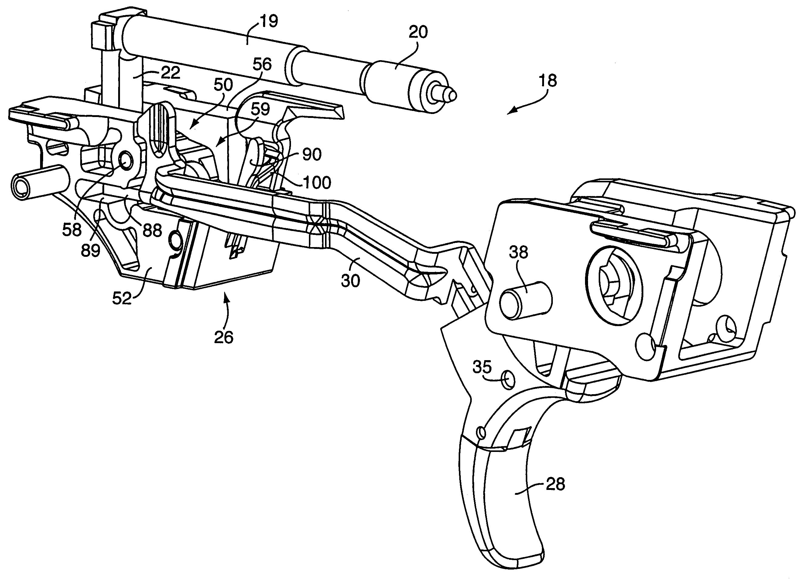
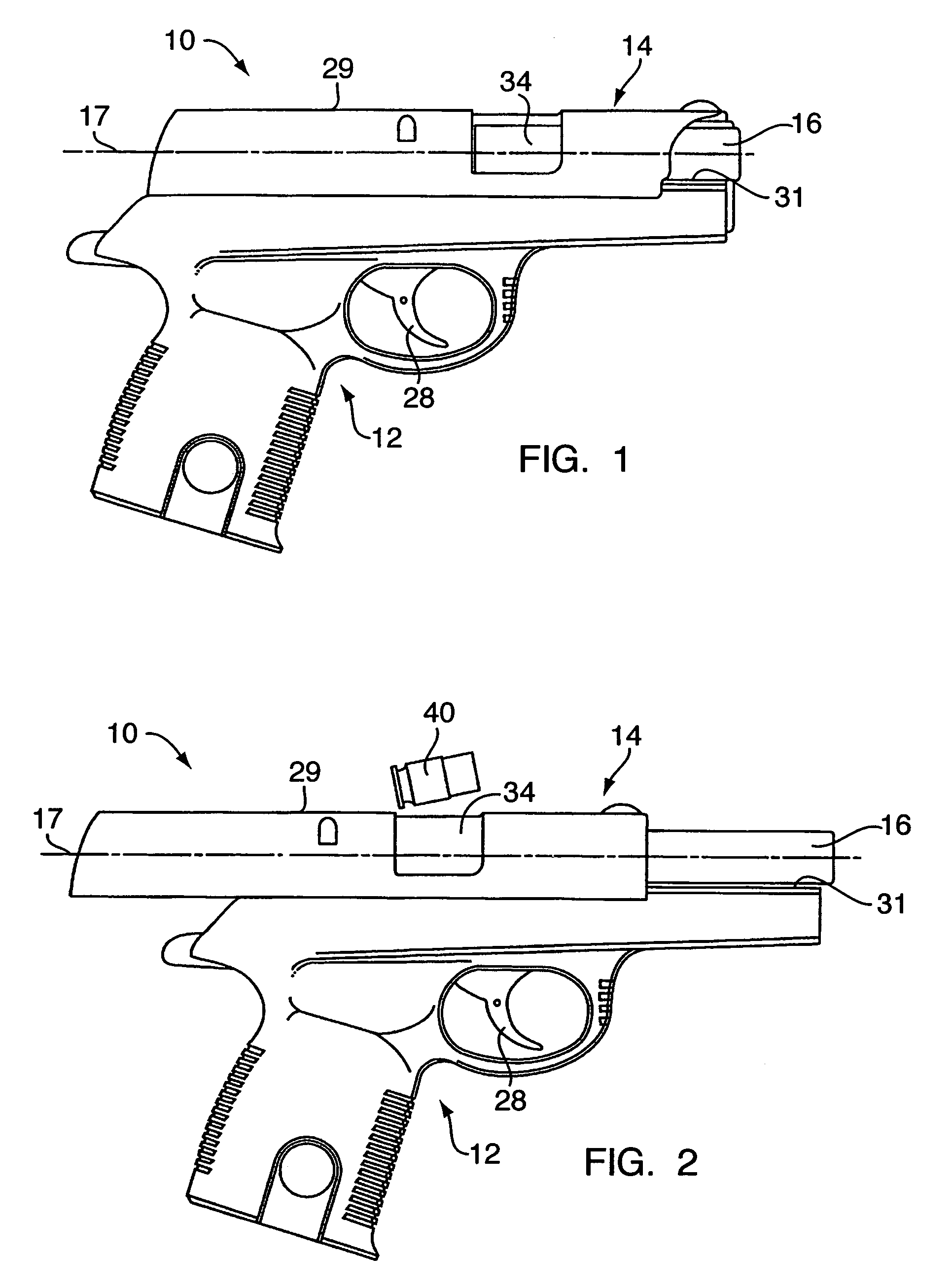
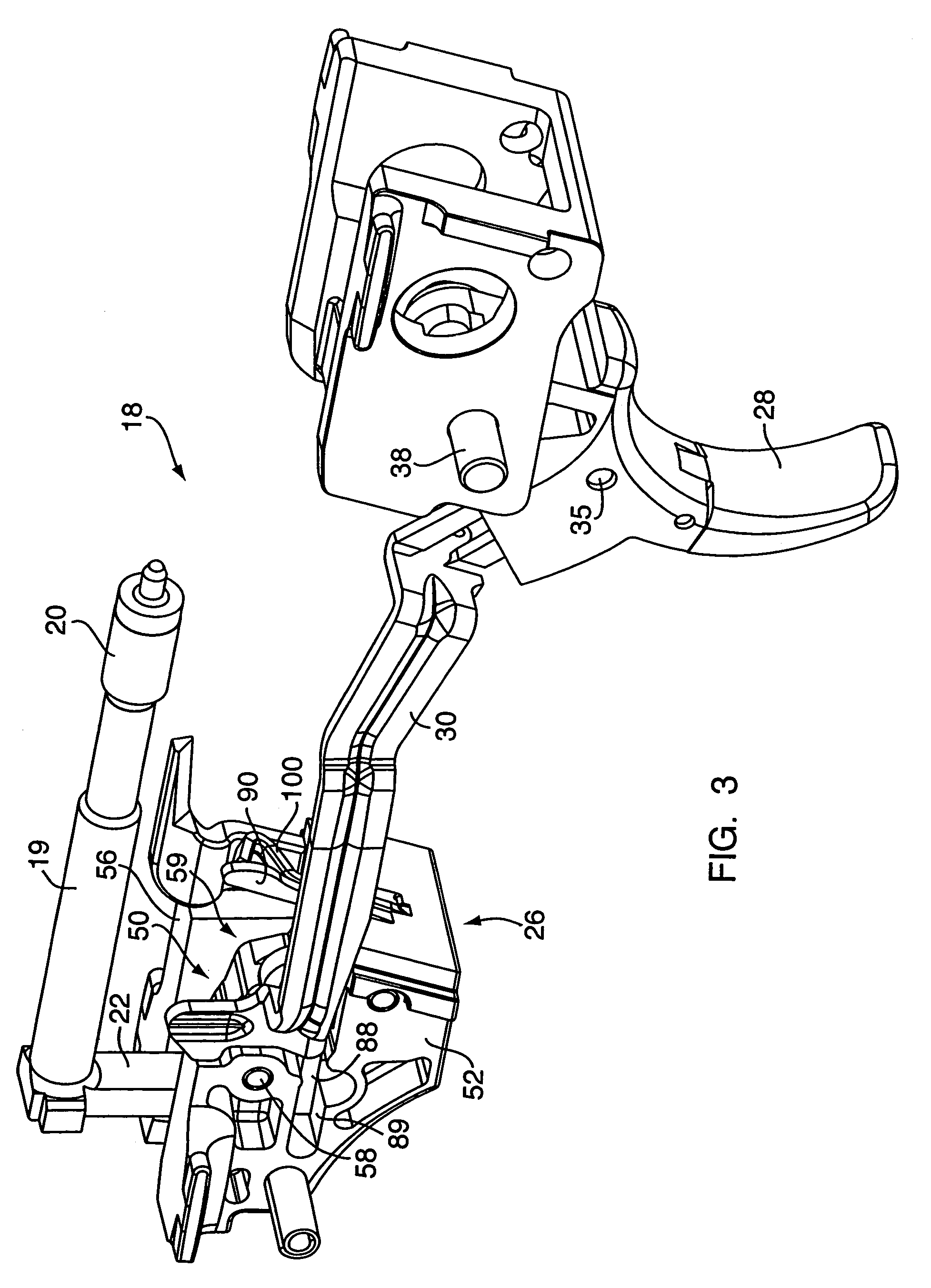
[0022]Referring to FIGS. 1 and 2, a semiautomatic pistol or handgun is shown generally at 10 and is hereinafter referred to as “handgun”10. The handgun 10 comprises a frame 12, a slide 14, a barrel 16, and a fire control mechanism 18 (see FIG. 3). The barrel 16 is disposed at the front aperture of the slide 14 and is cooperatively linked therewith, and, together with the slide 14, defines a longitudinal firing axis 17. The barrel 16 has a rearward end adapted for receiving an ammunition cartridge 40. A trigger 28 is pivotally mounted to the frame 12 to actuate the fire control mechanism to fire the handgun 10. The frame 12 is fabricated of a high-impact polymer material, metal, a combination of polymer and metal, or the like. The fire control mechanism or means 18 is provided for discharging a round of ammunition upon actuation of the trigger 28.

[0023]The slide 14 is fitted to opposingly-positioned rails 31 of the frame 12 to effect the reciprocal movement of the slide 14 along the ...


PUM


Abstract

A firearm includes a frame and a slide. A firing mechanism for the firearm includes a striker-type firing pin, a trigger, and a trigger bar. A sear inside the frame is pivotally balanced about a central fulcrum, and is biased in a first pivotal direction by a spring. In this position, a rear portion of the sear engages the firing pin. Actuation of the trigger causes the trigger bar to move rearwards for engagement of a forward portion of the sear. This pivots the sear in a second pivotal direction, against the spring, which releases the firing pin. The spring then causes the sear to pivot back for reengaging the firing pin when it returns to its rear position. Movement of the slide to a retired position causes the trigger bar to disengage from the sear (preventing discharge of the firearm) until the slide returns to a battery position.

Description

[0001]This application claims the benefit of the following U.S. Provisional Applications: Ser. No. 60 / 639,187; Ser. No. 60 / 638,594; Ser. No. 60 / 638,753; Ser. No. 60 / 638,593; Ser. No. 60 / 638,746; Ser. No. 60 / 638,592; Ser. No. 60 / 638,751; and Ser. No. 60 / 638,752, all filed Dec. 22, 2004, and all hereby incorporated by reference herein in their entireties.FIELD OF THE INVENTION[0002]The present invention relates to semiautomatic pistols or handguns and, more particularly, to fire control mechanisms for semiautomatic pistols or handguns.BACKGROUND OF THE INVENTION[0003]One type of fire control mechanism commonly used in semiautomatic handguns includes a hammer that is pivotable from a rearward cocked position to a forward position for impacting a firing pin. A sear releasably retains the hammer in the cocked position via a spring maintained in compression. When the trigger is moved, the sear is moved to release the hammer, which moves in response to the release of the stored energy in t...

Claims


Application Information

Patent Timeline
Patent Type & Authority Patents(United States)
IPC IPC(8): F41A17/36
CPCF41A19/28F41A19/12
Inventor CURRY, BRETT
Owner SMITH & WESSON
Why Eureka
Try Eureka