Exhaust throttle-EGR valve module for a diesel engine

a technology of exhaust gas module and engine, which is applied in the direction of machines/engines, mechanical equipment, transportation and packaging, etc., can solve the problem that motorized vehicles today are limited to the amoun

Inactive Publication Date: 2009-11-17
BORGWARNER INC
View PDF43 Cites 42 Cited by
  • Summary
  • Abstract
  • Description
  • Claims
  • Application Information

AI Technical Summary

Problems solved by technology

Due to both federal and state regulations, motorized vehicles today are limited to the amount of emissions in which they can release during operation.

Method used


Image

  • Exhaust throttle-EGR valve module for a diesel engine
  • Exhaust throttle-EGR valve module for a diesel engine
  • Exhaust throttle-EGR valve module for a diesel engine

Examples


Embodiment Construction

[0019]The following description of the preferred embodiment(s) is merely exemplary in nature and is in no way intended to limit the invention, its application, or uses.

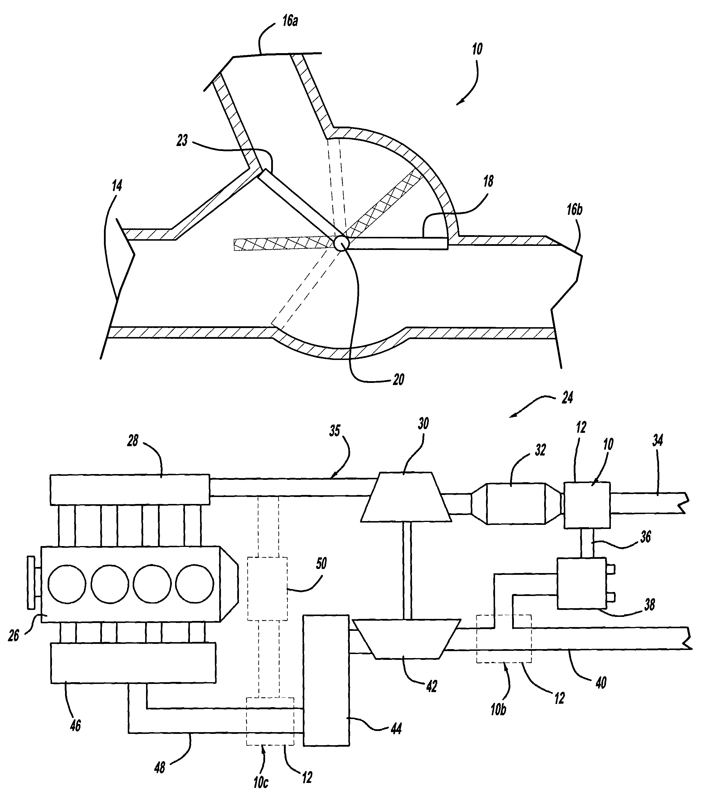
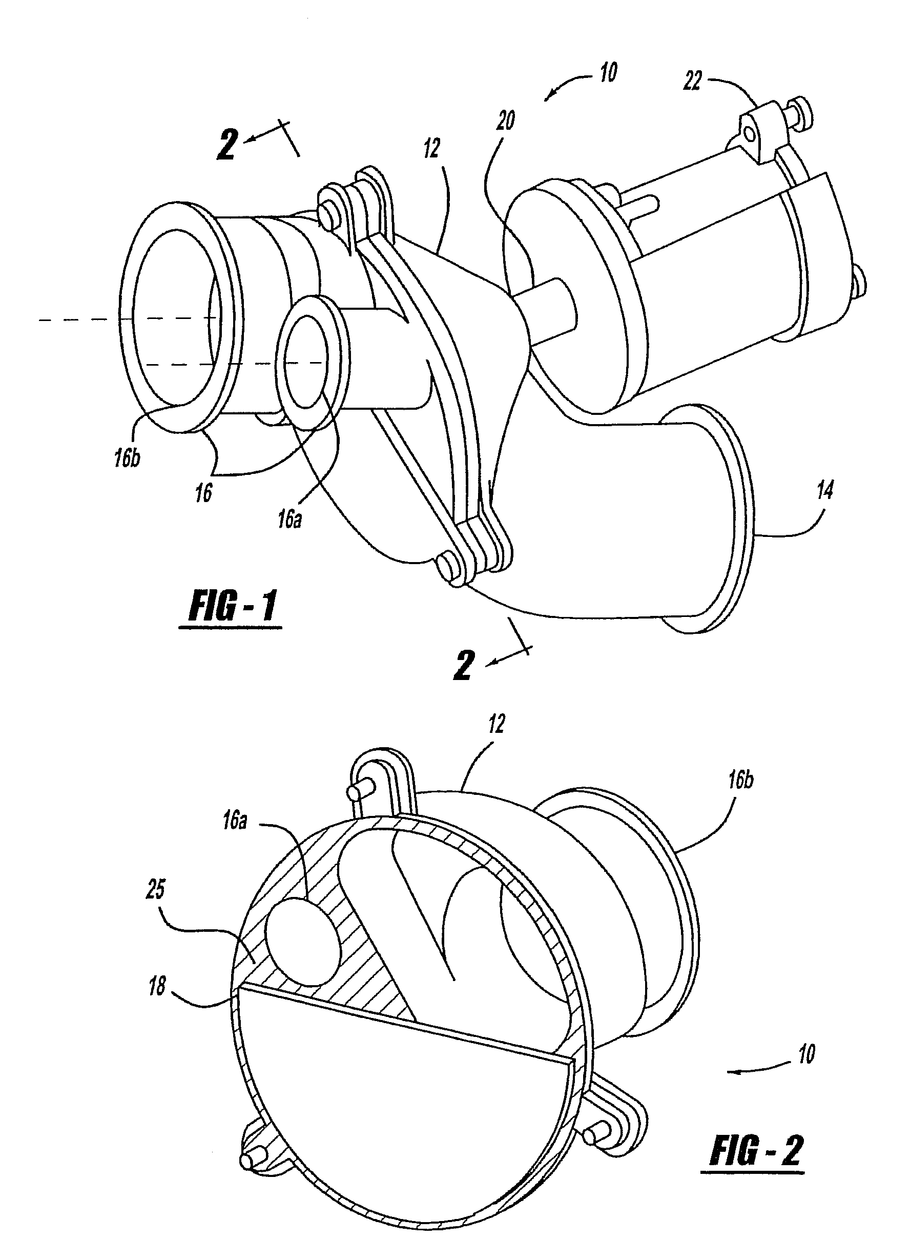
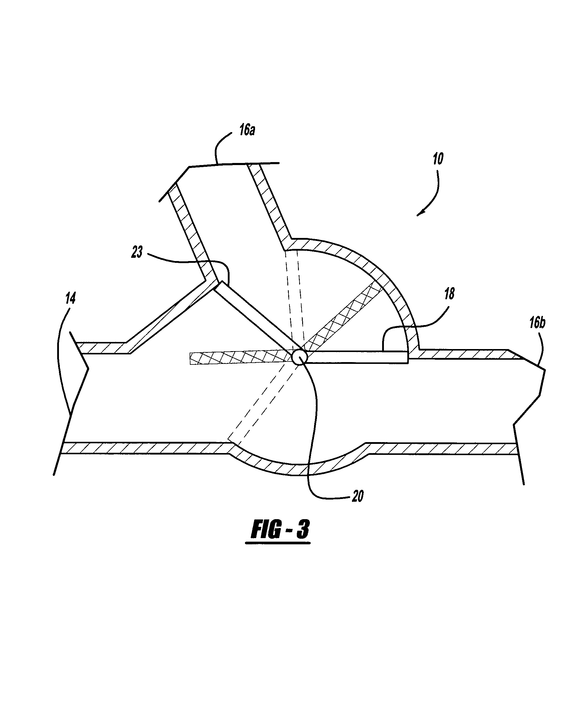
[0020]Referring to FIGS. 1-3, 5, and 6, a valve assembly or an exhaust throttle-exhaust gas recirculation valve module (ETVM) is generally shown at 10. The ETVM 10 has a housing 12 with a plurality of openings. The openings form at least one inlet 14 and at least one outlet 16. In a preferred embodiment, the housing 12 has one inlet 14 and two outlets 16. A first outlet 16a is an exhaust gas recirculation (EGR) path and a second outlet 16b is an exhaust path. The housing 12 also contains valve 18 which is used to direct the flow of gaseous fluid or exhaust gas inside the housing 12 by being placed in different positions with respect to the EGR path 16a and the exhaust path 16b.

[0021]A single actuator 20 is used to control the valve 18. In a preferred embodiment, the actuator 20 is operably connected to an electric mo...


PUM


Abstract

A valve assembly for use in an air management assembly having an engine, an exhaust side, and an intake side, where the valve assembly provides a housing, a plurality of openings in the housing, a valve in the housing, and an actuator operably connected to the valve. The housing is in fluid communication with the exhaust side and the intake side. The plurality of openings in the housing form at least one inlet and at least one outlet in the housing. The valve moves with respect to the plurality of openings.

Description

CROSS-REFERENCE TO RELATED APPLICATIONS[0001]This application is a continuation-in-part of Non-Provisional application No. 11 / 475,629, filed Jun. 27, 2006, which was a continuation-in-part of PCT Application No. PCT / US06 / 04345, filed Feb. 7, 2006, and a continuation-in-part of PCT Application No. PCT / US06 / 04345, filed Feb. 7, 2006, which both claim the benefit of U.S. Provisional Application No. 60 / 696,854, filed Jul. 6, 2005 and Provisional Application No. 60 / 650,752, filed Feb. 7, 2005.FIELD OF THE INVENTION[0002]The present invention relates to an exhaust gas module that directs gaseous fluid to a plurality of openings.BACKGROUND OF THE INVENTION[0003]Due to both federal and state regulations, motorized vehicles today are limited to the amount of emissions in which they can release during operation. One way of reducing the amount of emissions released by the vehicle is to include an air management assembly having an exhaust gas recirculation (EGR) valve. The EGR valve directs at ...

Claims


Application Information

Patent Timeline
Patent Type & Authority Patents(United States)
IPC IPC(8): F02B33/44F02M25/07F16K11/085
CPCF02M25/0709F02M25/0713F02M25/0718F02M25/0719F02M25/0772F02M25/0773F02M25/0796F02B29/0406Y02T10/121F02M25/074F02M25/0727F02M26/16F02M26/06F02M26/10F02M26/15F02M26/23F02M26/35F02M26/53F02M26/54F02M26/71Y10T137/86871Y10T137/86855F02D21/08
Inventor JOERGL, VOLKERKIENER, TIMMWEBER, OLAFTHORPE, BRUCE
Owner BORGWARNER INC
Why Eureka
Try Eureka