Automatic gate and associated method for permitting or preventing access

a technology of automatic gate and associated method, applied in the field of automatic gate, can solve the problems of obstructing the passage, irritating passengers, and inability to operate normally, and achieve the effects of avoiding the damage of glass barriers

Inactive Publication Date: 2009-11-17
AUTOMATIC SYSTEMS
View PDF17 Cites 19 Cited by
  • Summary
  • Abstract
  • Description
  • Claims
  • Application Information

AI Technical Summary

Benefits of technology

[0018]The invention thus makes it possible to avoid any risk that a passenger can commit fraud by recovering his ticket before the opening of the flap.
[0022]This shape makes it possible to constitute an obstacle preventing passage whilst allowing the flap to be completely retracted in the gate's opening position.
[0036]the cells in the upper or middle rows, situated downstream of the flap are suitable for detecting the passage of a person or of a child from downstream to upstream of the gate and for controlling the closing of the flap in order to prevent said person from turning back.

Problems solved by technology

The main drawbacks of these known solutions are the following:
In the case of three bars turnstiles, the turnstile is moved manually and the bars of the turnstile permanently obstruct the passage, annoying passengers, in particular if they have luggage.
In revolving-gate systems, the gate occupies a large space which cannot be used for detection equipment.
The systems with a glass obstacle are fragile i.e. they cannot withstand impacts.
Current systems have a low reliability level as the obstacle can inhibit detection of the user's advance.
It is difficult to carry out passage detection at different heights.
The fact that the ticket is recovered before passing the obstacle does not guarantee that the person has actually passed through.
Moreover, this recovery does not invite the person to pass through, as the turnstile remains static unless the person makes a movement to open it himself.

Method used


Image

  • Automatic gate and associated method for permitting or preventing access
  • Automatic gate and associated method for permitting or preventing access
  • Automatic gate and associated method for permitting or preventing access

Examples


Embodiment Construction

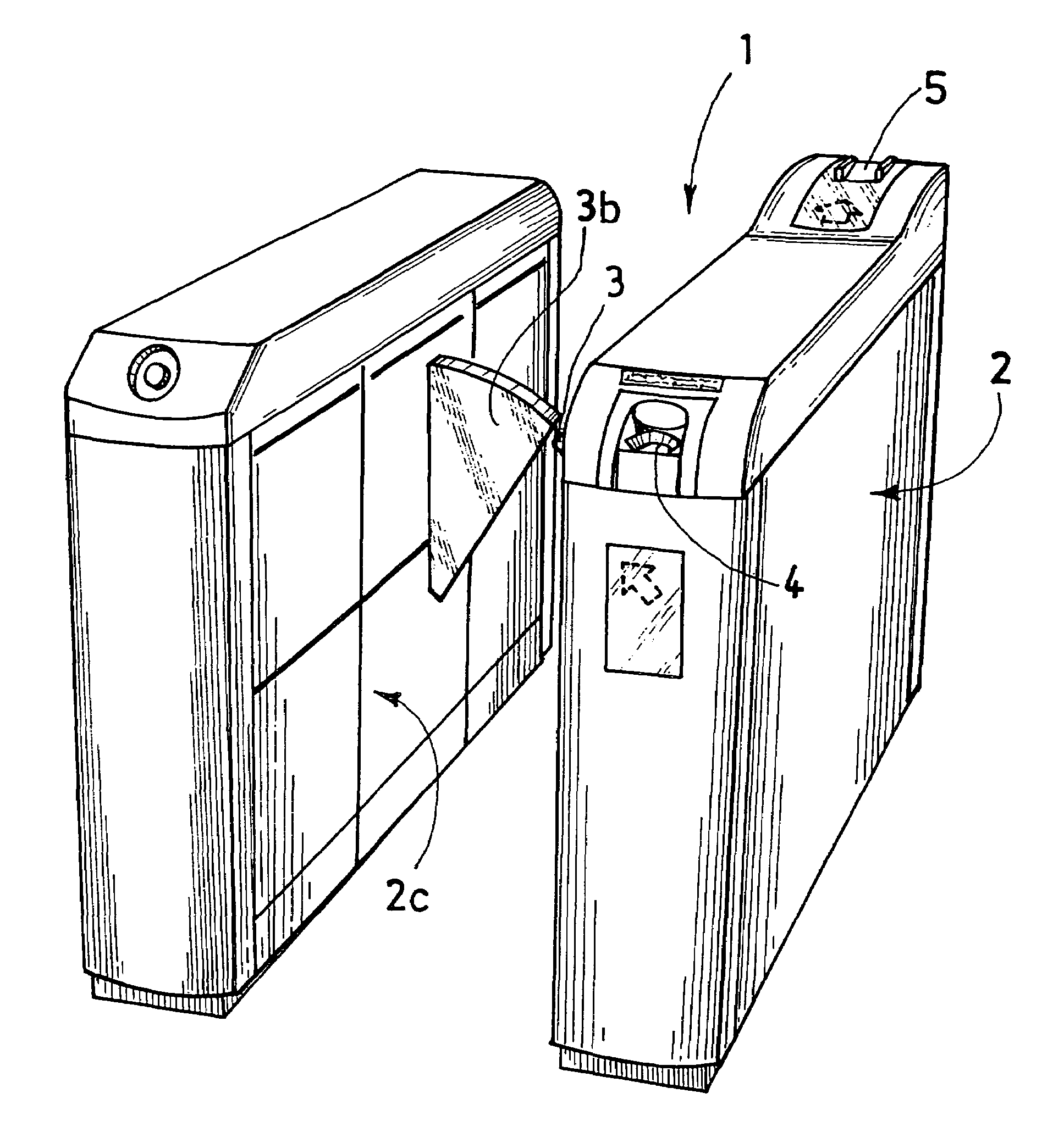
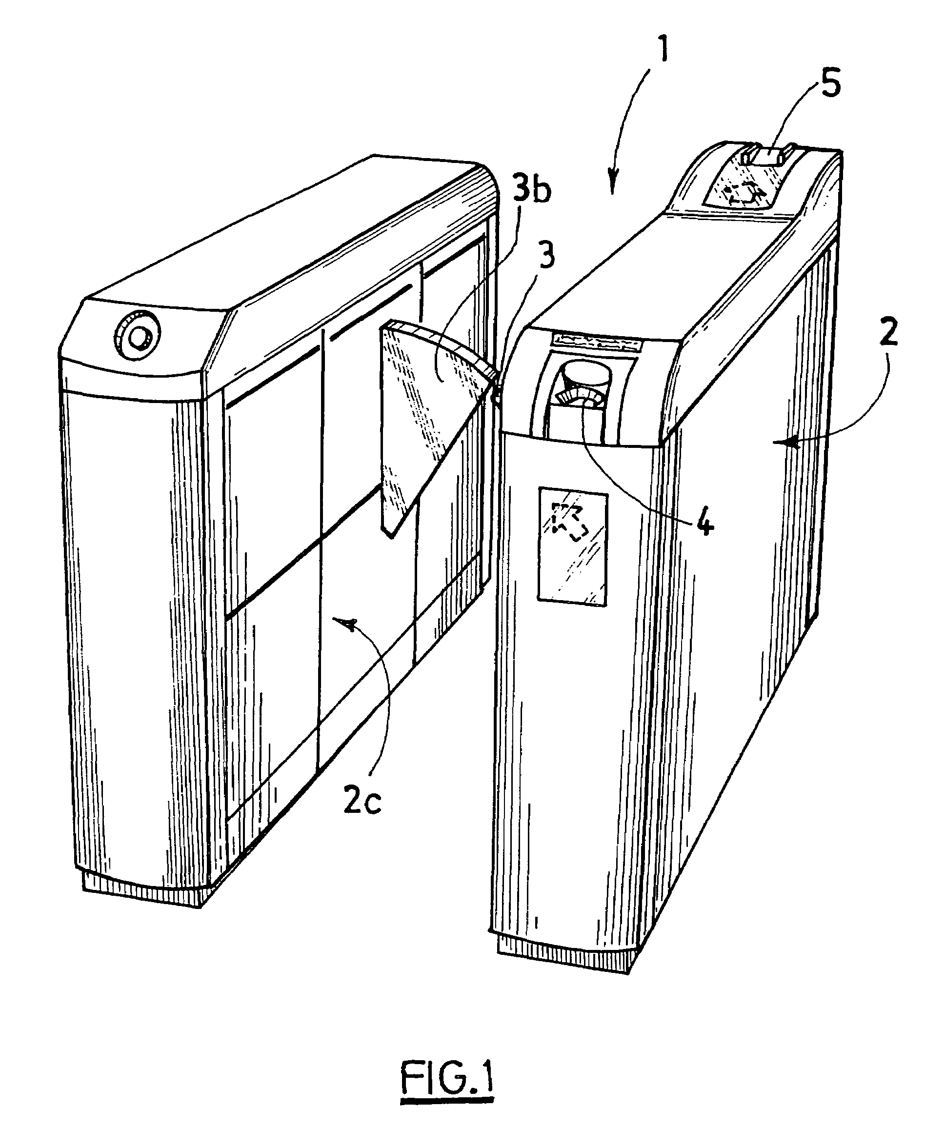
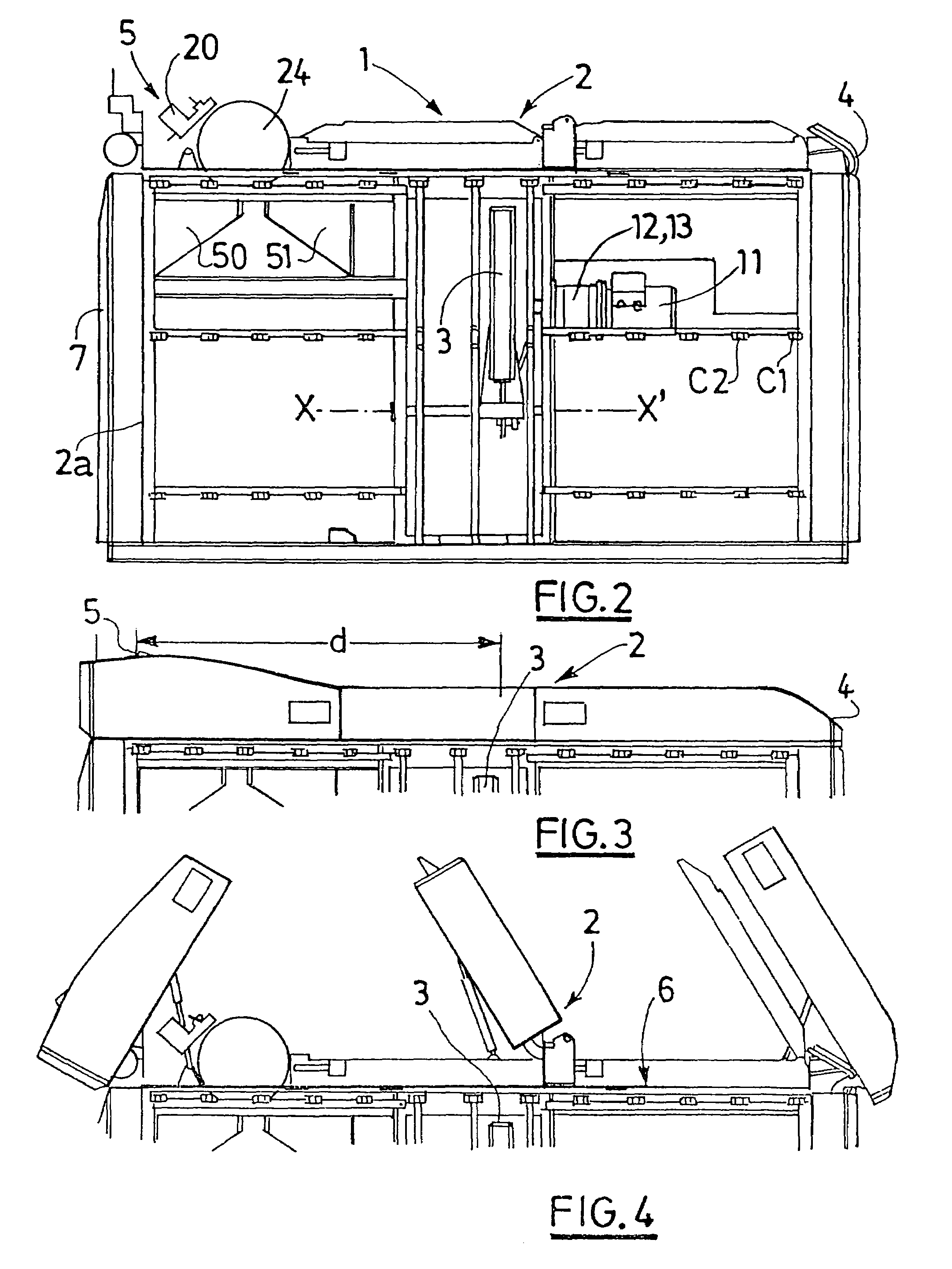
[0070]In the embodiment represented in FIGS. 1 to 5, the automatic gate 1 for permitting or preventing access to a space or a transport vehicle, in particular to a boarding lounge or an aeroplane, comprises a vertical and elongated frame 2 constituting a closed box in the shape of a parallelepiped. This frame 2 carries a flap 3 which is mobile between a closed position (see FIG. 5) in which this flap 3 forms a barrier preventing the passage of a passenger along the frame 2 and an open position in which the flap 3 allows this passage.

[0071]The upstream end of the frame 2 relative to the direction of movement of the passenger comprises, close to the upper face of the frame, an input slot 4 for an access ticket and the downstream end of the frame 2 comprises, on the upper face of the frame, an output slot 5 for this ticket. The frame 2 contains means which are described in detail hereafter for controlling the displacement of the flap 3 between the two abovementioned positions. The fram...


PUM


Abstract

Gate (1) including a vertical extended frame (2); at least one flap (3) which may be displaced between a closed position in which the flap prevents the passage of a person and an open position in which the flap permits the passage, elements for reading an access ticket, elements for controlling the displacement of the flap between the two positions, a lateral face to the frame (2), adjacent to the passage for the person provided with at least two rows of detector cells (C1-C33) cooperating with elements for preventing the opening of the flap when the cells detect an abnormal situation, one row of which extends to both sides of the flap above a line (L) situated at the mid-height of the frame and the other row is located close to the line.

Description

FIELD OF THE INVENTION[0001]The present invention relates to an automatic gate for permitting or preventing access to a space or a transport vehicle, in particular to a boarding lounge or an aeroplane.[0002]Generally the invention applies to access to boarding lounges, boats, aeroplanes or any means of public transport or to buildings, access to airlines' lounges in airports, and to duty-free zones.BACKGROUND OF THE INVENTION[0003]The most conventional solutions are three bars turnstiles controlled by the reading of a valid transport ticket.[0004]Low gates with mobile, sliding, revolving or swinging glass flaps are also known.[0005]The main drawbacks of these known solutions are the following:[0006]The speed of release of passage is very slow with these different systems as the masses in movement are considerable and the inertia to be overcome is high.[0007]In the case of three bars turnstiles, the turnstile is moved manually and the bars of the turnstile permanently obstruct the pa...

Claims


Application Information

Patent Timeline
Patent Type & Authority Patents(United States)
IPC IPC(8): G06K5/00E06B11/08G07C9/02
CPCG07C9/02E06B11/085G07C9/10
Inventor VANDYCK, DANIELROYEN, FRANCOISGOSSELIN, HERVE
Owner AUTOMATIC SYSTEMS
Why Eureka
Try Eureka