Tools for femoral resection in knee surgery

a femoral resection and tool technology, applied in the field of knee arthroplasty methods and tools, can solve the problems of inability to adjust the degrees of freedom simultaneously, the current tools do not permit the attachment of trackers, and the prior art instruments used to determine the correct plane for tibial and femoral resection in total knee arthroplasty are not well suited to computerized systems,

Active Publication Date: 2009-11-17
HOWMEDICA OSTEONICS CORP
View PDF93 Cites 79 Cited by
  • Summary
  • Abstract
  • Description
  • Claims
  • Application Information

AI Technical Summary

Benefits of technology

The method described involves working alongside an electronic navigator that helps surgeons perform procedures accurately by guiding them during surgery. This can include selecting where they are located at their desired locations before making any changes needed, adding anchor devices like wires into existing spaces around it (such as muscles), inserting markers along specific areas within the body, aligning tools correctly, etc., which help improve accuracy when performing these operations.

Problems solved by technology

The technical problem addressed in this patent text is the need for improved tools and methods for accurately resecting bones and replacing them with artificial components in total knee arthroplasty procedures. The existing tools used for determining the correct planes for resection are not well-suited for use with computerized systems and do not allow for the attachment of trackers, which are necessary for proper navigation.

Method used


Image

  • Tools for femoral resection in knee surgery
  • Tools for femoral resection in knee surgery
  • Tools for femoral resection in knee surgery

Examples


Embodiment Construction

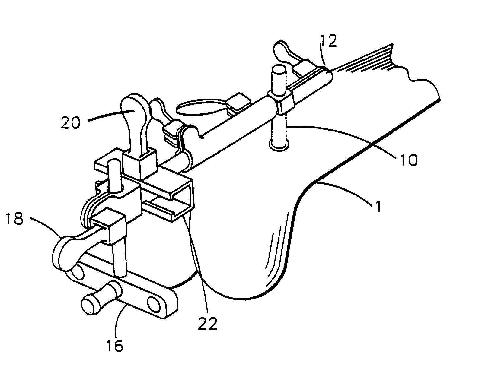
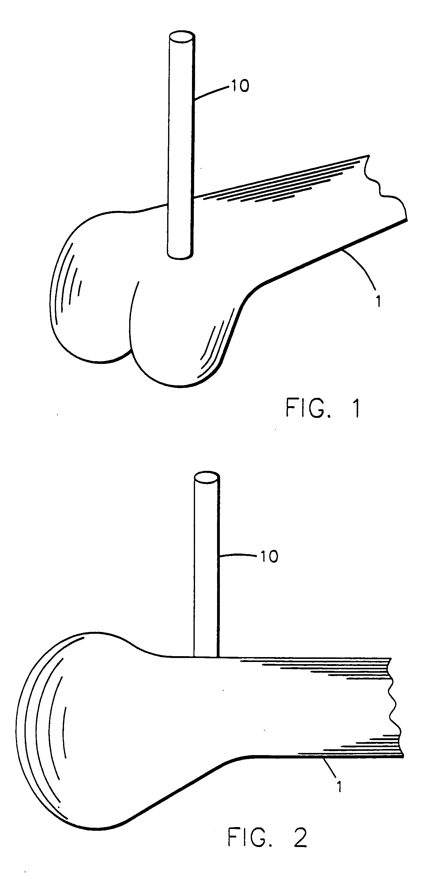
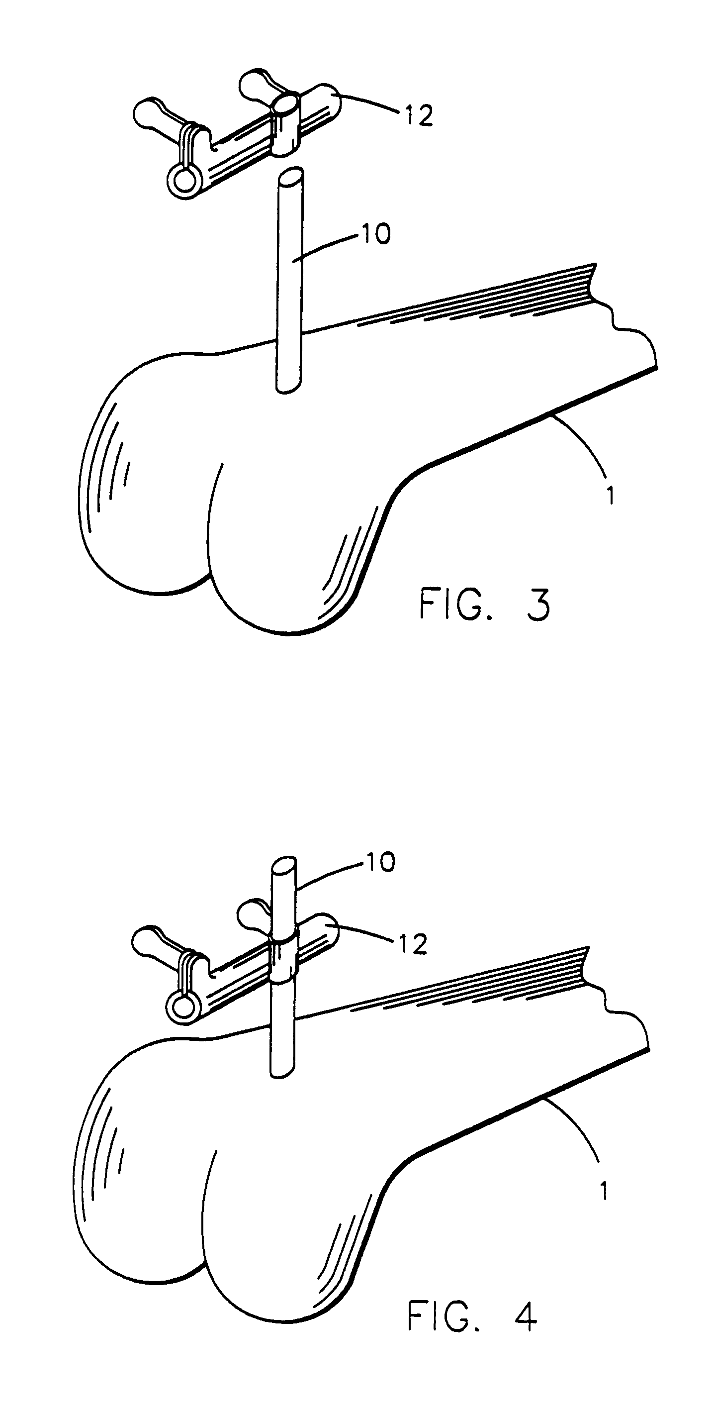
[0044]Turning now to the Figures, the apparatus of the invention will be best understood by a description of the methods of the invention with reference to the Figures. As shown in FIGS. 1 and 2 an anchoring device 10 is installed in the bone 1 in a region proximal to the lateral anterior cortex and within the incision. The location for the anchoring device may be chosen by eye or with the aid of the tracking / navigation software, with an emphasis on paralleling the anchoring device body to the sagital plane. As shown in the Figures, the anchoring device 10 is a pin which is screwed into the bone. Other anchoring devices such as plates could be used, however.

[0045]With the anchoring device 10 in place, the alignment guide 12 is lowered on to it as shown in FIGS. 3-5. As seen best in FIG. 5, the alignment guide 12 has three cam locks 12a, 12b, 12c. The cam lock 12a allows the alignment guide to be adjusted according to flexion-extension angle relative to the anchoring device 10. The c...


PUM


Abstract

Tools for resecting the femur include an anchoring device, a three-way alignment guide and a six way alignment guide attachable to the anchoring device, a resection guide attachable to the three-way alignment guide and equipped with couplings for trackers, an A-P sizer, a femoral sizing block bushing attachable to the six-way alignment guide, a 4-in-1 femoral cutting block, a 5-in-1 positional alignment guide attachable to the six-way alignment guide, a pair of diodes, and a 5-in-one cutting block. Methods of utilizing the apparatus are also disclosed.

Description


Claims


Application Information

Patent Timeline
Owner HOWMEDICA OSTEONICS CORP
Why Eureka
Try Eureka