Tools and methods for orthopedic surgery

a technology for orthopedic surgery and tools, applied in the field of tools and methods for orthopedic surgery, can solve the problems of skin, muscle and tendons, difficult and/or clumsy procedures, and requiring additional personnel in the surgery room, and achieve the effects of safe broaching/cutting/drilling, convenient access, and effective work

Inactive Publication Date: 2010-01-28
BOTIMER GARY
View PDF11 Cites 12 Cited by
  • Summary
  • Abstract
  • Description
  • Claims
  • Application Information

AI Technical Summary

Benefits of technology

[0013]The femur adjustment tool “lateralizes and lifts” the top end of the patient's femur into, and preferably holds the femur in, the desired position so that the femur end may be conveniently accessed and effectively worked on during the surgery. The femur adjustment tool of the present invention comprises a fulcrum member that is received against/in the acetabulum, and a lever unit connected to said fulcrum member. The femur adjustment tool acts as a first-class lever system for lifting and lateralizing the femur, wherein the preferred fulcrum member is located between the input effort and the output load. In operation, the handle end is pushed, which causes the lever unit to swing about the fulcrum that is located in/on the acetabulum, overcoming the resistance force on the femur side, which is the femur's resistance to movement due to it being in a location inside the patient's body that is normal/natural except that it has been separated from the hip socket. The fulcrum is nearer the femur contact end than the handle end, to provide the benefit of leverage. The fulcrum member preferably comprises a ball-like, spherical, partly spherical, or other rounded or curved (and preferably smooth) portion that contacts and pivots on the acetabulum, so that the acetabulum is not damaged or marred by the fulcrum member during use of the femur adjustment tool.
[0014]The preferred tissue protector and broach guide tool may serve multiple functions during surgery, preferably including shielding tissue from possible damage during broaching or other bone cutting/drilling procedures and guiding the broaching or other cutting/drilling tool for effective, accurate, and safe broaching/cutting/drilling. In addition, the preferred protector and guide tool may serve as a soft tissue retractor to assist in control of the soft tissue around or inside the surgical incision. The preferred tissue protector and broach guide tool comprises an elongated, preferably rigid arm that bends or curved at approximately 20-45 degrees, to form a handle portion and a guide portion. The handle portion is adapted for being held and/or forced by a user for placing a tip of the guide portion against a surface of the femur, so that a curved/concave surface of the guide portion is generally aligned with, and reaches to, the femur portion into which the broaching tool will be forced to create

Problems solved by technology

Conventionally, this “lateralization” and “lifting” has been done by hand by one or more surgical assistants, by manipulating the patient's leg to push the femur top toward the incision opening, therefore requiring additional, trained surgery room personnel and resulting in a difficult and/or clumsy procedure.
The area of the incision and the top end of the femur include

Method used


Image

  • Tools and methods for orthopedic surgery
  • Tools and methods for orthopedic surgery
  • Tools and methods for orthopedic surgery

Examples


Embodiment Construction

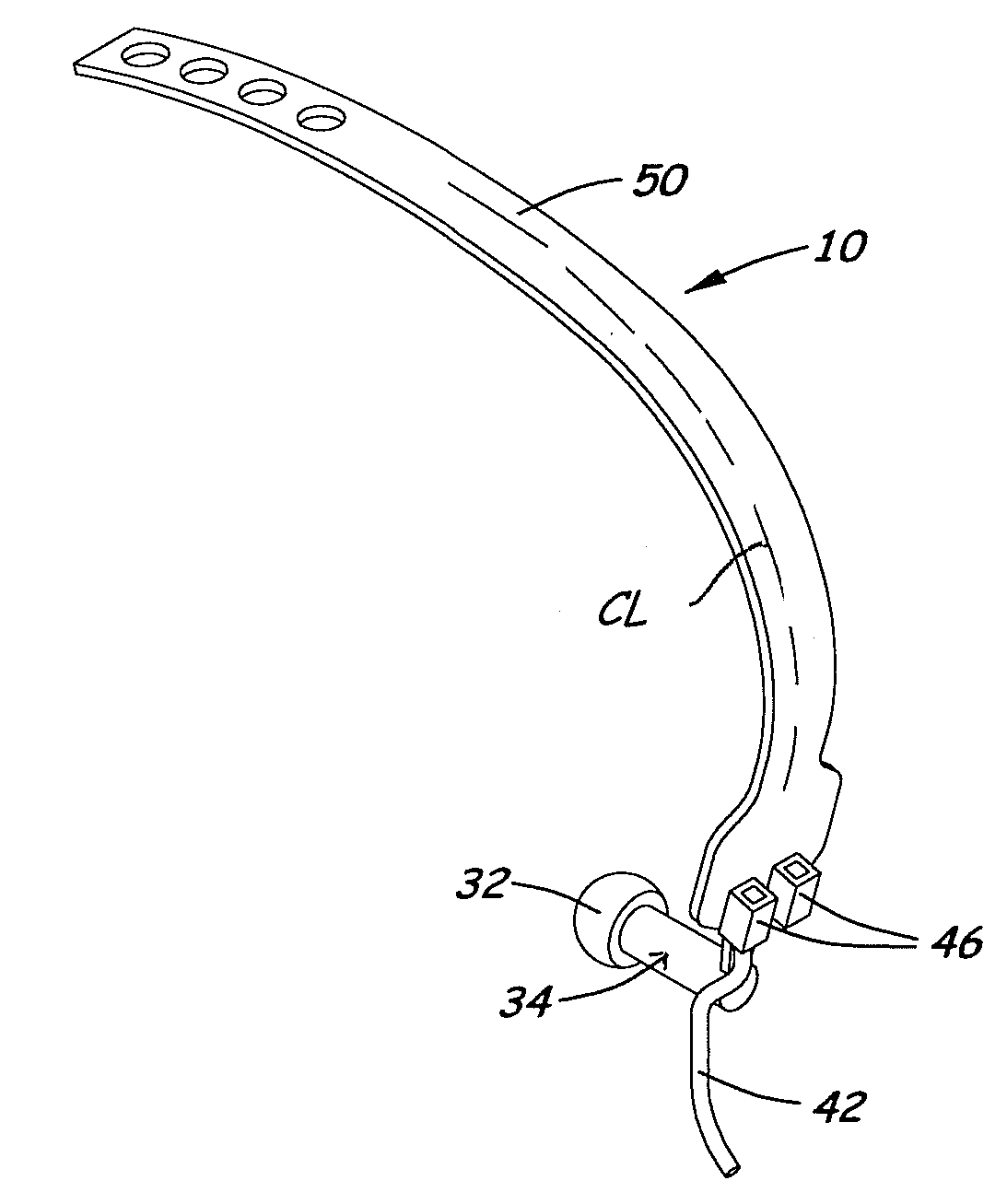
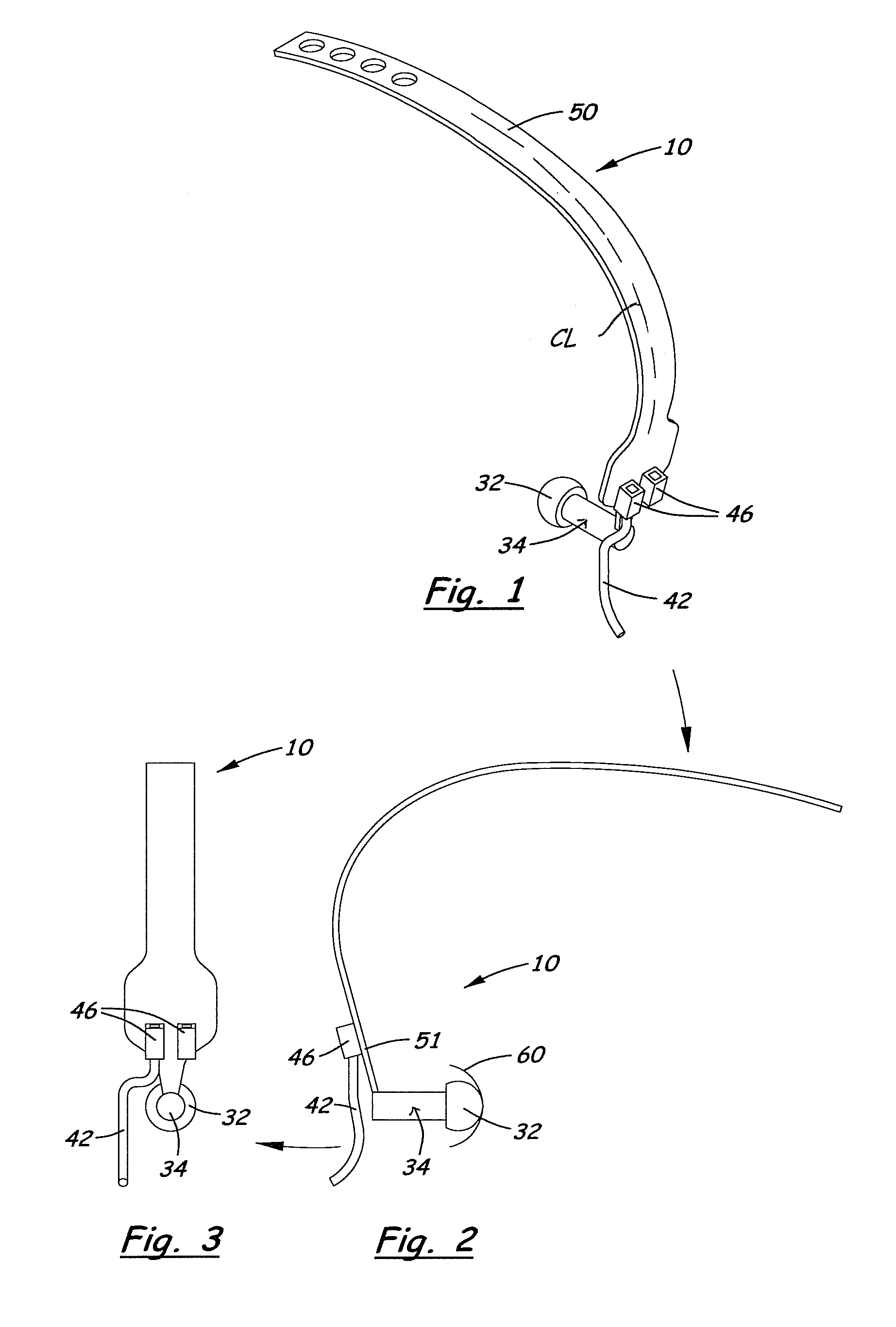
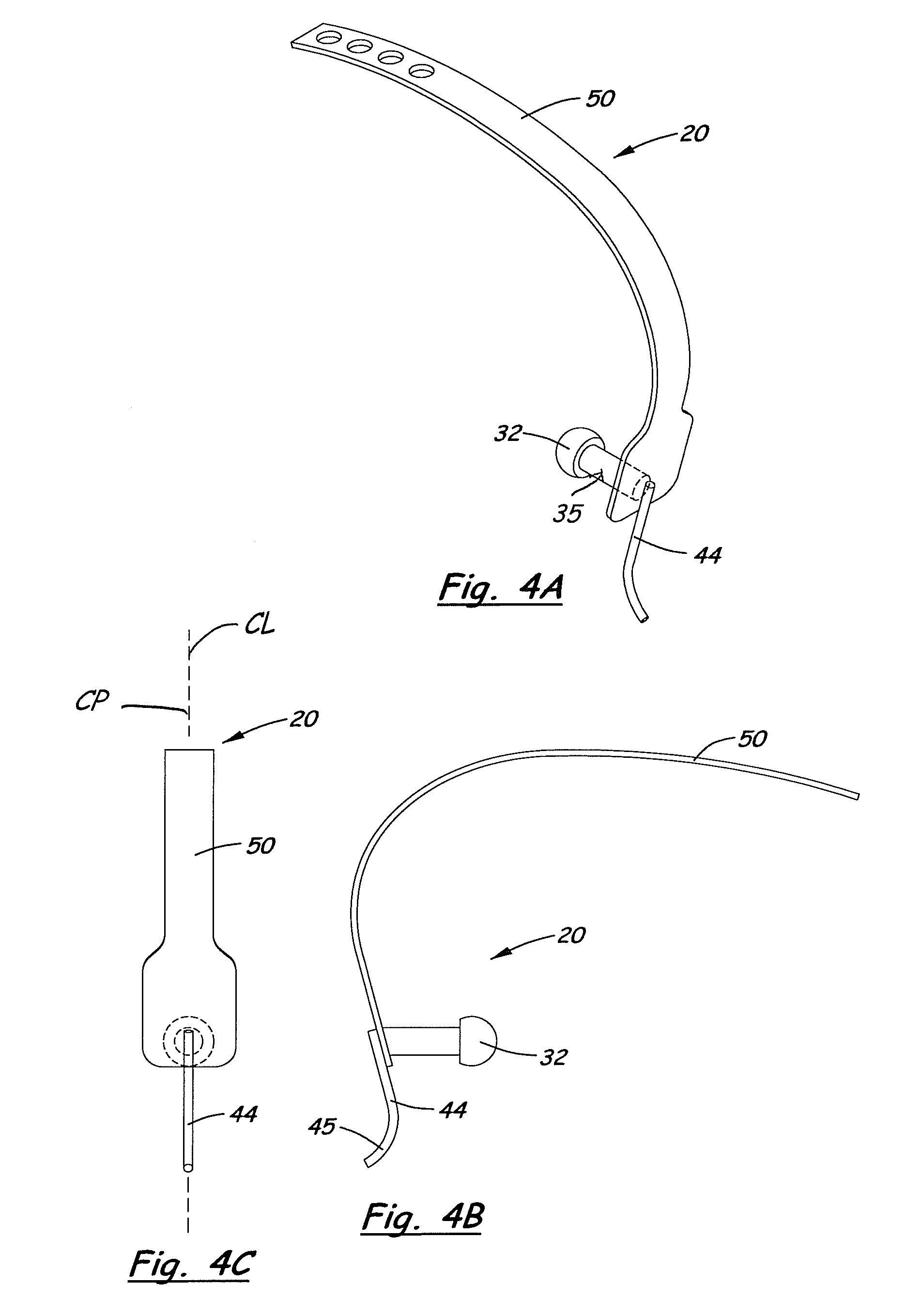
[0047]Referring to the Figures, there are depicted several, but not the only, embodiments of the present invention. FIGS. 1-3, 4A-C, 5A-D, 6A and B, 13A and B, 14A and B, 15, 16 and 19 portray preferred embodiments and use of the femur adjustment tool. FIGS. 7-12, and 17-19 portray preferred embodiments and use of tissue protector and guide tool. FIGS. 20-31 portray preferred embodiments and use of the invented bone clamp. Either one, two or three of the invented tools may be used to improve arthroplasty, especially hip and knee arthroplasty. The three preferred tools, and methods of using them, are discussed in detail below, and it should be understood that the individual tools are not necessarily limited to the embodiments shown and detailed herein, and that, while the preferred methods are described herein, that other uses for the tools, individually or various combinations of two or more, are included within the broad scope of the invention.

Femur Adjustment Tool

[0048]The preferr...


PUM


Abstract

Tools may be used individually and/or in combination to allow minimally invasive and safer orthopedic surgery. A femur adjustment tool lifts and lateralizes the proximal end of the femur during hip replacement surgery by pivoting on a ball temporarily placed in the acetabulum. A tissue protection and broach (rasp, cutting, drilling) guide tool may retract tissue at the incision, protect tendons and soft tissue, and provides a curved, elongated surface that cradles and guides the broaching tool. A tip of the main body of the protection and guide tool, and a hook protruding from the main body, may extend along opposite surfaces of the femur to help “capture” a portion of the femur for tool stability and to effectively and positively protect the piriformus tendon that will reside in the “V” between the hook and tip. A bone clamp is used when a generally transverse cut is made across a bone, for example, a knee surgery proximal tibial cut, wherein the clamp improves control of the bone portion for safer freeing of the bone portion from soft tissue and extracting the bone portion from the incision. A broad, flat plate of the bone clamp may be slid between the bone and the bone portion into the narrow space that has been created by cutting the bone, and a relatively narrow gripping member may be slid along/across the opposing surface of the bone portion, which allows the narrow gripping member to fit into the intercondylar notch of the femur.

Description

[0001]This application claims benefit of Provisional Application 61 / 083,460, filed Jul. 24, 2008; Provisional Application 61 / 083,514, filed Jul. 24, 2008; Provisional Application 61 / 092,837, filed Aug. 29, 2008; and Provisional Application 61 / 121,795, filed Dec. 11, 2008; and Provisional Application 61 / 155,148, filed Feb. 24, 2009; wherein the entire disclosures of which are incorporated herein by this reference.BACKGROUND OF THE INVENTION[0002]1. Field of the Invention[0003]This invention relates generally to tools and methods for orthopedic surgery. In one group of embodiments, the tool and methods are specially-adapted for hip replacement or other hip surgery. In another group of embodiments, the tool and methods are specially-adapted for knee replacement and other knee surgery. More specifically, the invention is a system, and individual tools, for improved hip and / or knee arthroplasty procedures and results. One of the tools is used to conveniently move / lift the femur of the pa...

Claims


Application Information

Patent Timeline
IPC IPC(8): A61F5/00
CPCA61B17/025A61B17/175A61B17/2812A61B2017/0275A61B17/8866A61B2017/00477A61B17/282
Inventor BOTIMER, GARY
Owner BOTIMER GARY
Why Eureka
Try Eureka