Arthroscopic knot pusher and suture cutter

a pusher and suture technology, applied in the field of suture cutting equipment, can solve the problems of undesirable access to tissue in this manner, time-consuming suture cutting of tissue during surgical procedures, and difficulty in particular, so as to prevent suture from falling.

Active Publication Date: 2015-05-21
CETERIX ORTHOPAEDICS
View PDF3 Cites 13 Cited by
  • Summary
  • Abstract
  • Description
  • Claims
  • Application Information

AI Technical Summary

Benefits of technology

[0008]In general, described herein are surgical knot pusher and suture cutter apparatuses, and methods of using them to position a knot and cut the suture. These apparatuses (which include devices for knot pushing / suture cutting, and system including such devices) typically include a control that is configured to open a portion of the distal end of the apparatus for loading a suture laterally at the distal tip region; the same (or a different) control may be configured to drive a cutter for cutting a prescribed length of suture relative to a pushed knot. Any of the devices described herein may include a safety (e.g., safety release, cutter release, cutter safety, etc.) that maybe normally engaged to prevent the cutter from cutting a suture in the distal end of the device, but may be selectively disengaged to allow the cutter to cut a suture. The safety may be positioned with the control on the handle of the device, so that a user may operate the control for opening / loading the device and for cutting the suture with a single finger (e.g., the thumb), and may engage / disengage the safety with another finger or fingers (e.g., the index finger). The safety may be disengaged, allowing cutting by the cutter, by pressing on the safety and concurrently activating the control to drive the cutter to cut the suture. Any of these devices may also include a lock, stop or other feature (such as a “lock out tab”) that prevents the suture from falling out of the distal end of the device, even when force is applied against the loading portion of the device (e.g., an inner mandrel or inner member that can be displaced to allow loading of the suture) by a knot or other structure. Any of these device, and particularly those with a lock or other feature that prevents dropping of the suture even when applying force against the suture loading region, may also include a thumb ring at the proximal end that may be used by a surgeon to manipulate and position the device.
[0013]In any of the variations of the apparatuses described, the control may be a slider that is configured to be operated with a single finger to control the motion of both the inner member (e.g., sliding and / or rotation) and to control the axial motion of the cutter. For example, sliding the control (slider) proximally (back toward the user's hand) against a return or biasing force may “open” the lateral slot so that a suture can be captured therein. Releasing the slider, or moving the slider back distally, may restore the inner member (inner plunger member, etc.), closing off a portion of the lateral slot and may lock a suture within the cavity formed by the inner member and the inner diameter of a portion of the elongated holding tube.
[0031]In variations in which the inner member / mandrel is axially movable (slideable) to open the lateral slit on the distal end of the elongate holding tube, a lock out tab may be configured to be released by the operation of the control. In some variations the lock out tab is a strip of material (e.g., rigid material) that connects to the inner member and another portion of the device (e.g., the handle) to hold it secure relative to the elongate holding tube. This may prevent the inner member from sliding proximally when the knot is pushed or pulled against the distal end of the inner member / mandrel, which could otherwise disengage the inner member and allow the suture to fall out of the apparatus. For example, a lock out tab may be configured to be released by deflecting the lock out tab away from the inner mandrel with the application of a threshold force.

Problems solved by technology

Suturing of tissue during surgical procedures is time consuming and can be particularly challenging in difficult to access body regions and regions that have limited clearance, such as regions partially surrounded or covered by bone.
However, in many cases, accessing the tissue in this manner is undesirable, increasing recovery time, and exposing the patient to greater risk of infection.
Although many such devices are available for endoscopic, arthroscopic, and / or percutaneous use, these devices suffer from a variety of problems, including limited ability to navigate and be operated within the tight confines of the body, risk of injury to adjacent structures, problems controlling the position and / or condition of the tissue before, during, and after passing the suture, as well as problems with the reliable functioning of the suture passer.
Further, when performing surgery, such as arthroscopic surgery, suture knot placement can be an important yet difficult step.
However, such placement of knots and cutting of the knots typically requires the use of two separate tools, further complicating the surgical process.

Method used


Image

  • Arthroscopic knot pusher and suture cutter
  • Arthroscopic knot pusher and suture cutter
  • Arthroscopic knot pusher and suture cutter

Examples


Embodiment Construction

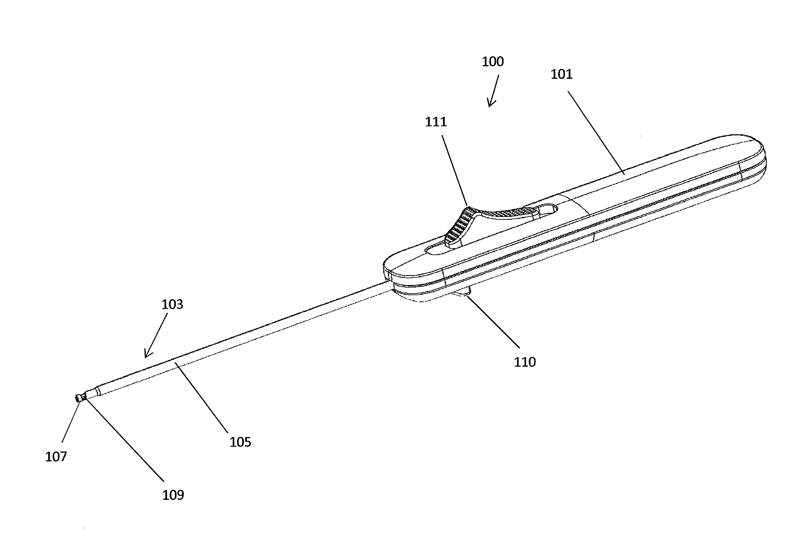
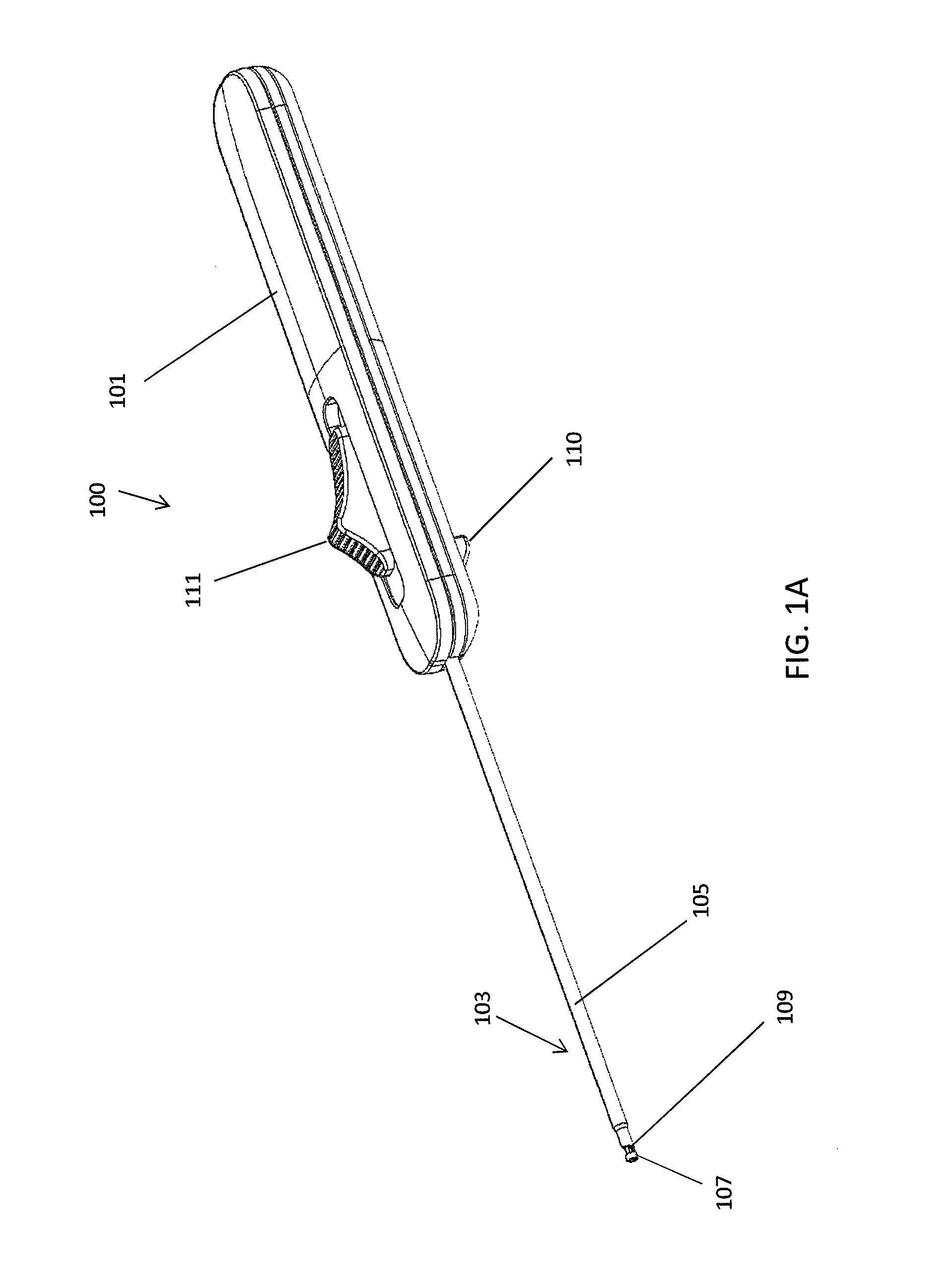
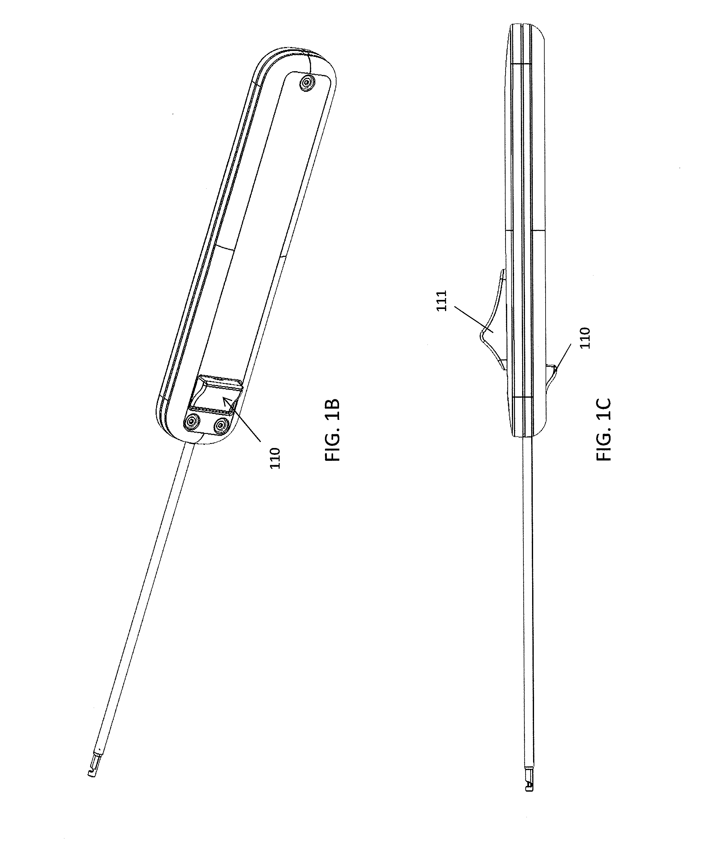
[0055]Described herein are combination knot pusher and suture cutter apparatuses for manipulating (e.g., pushing) a pre-tied knot in a suture to a desired location and then for cutting excess suture proximal to the knot. The apparatuses described herein may include a handle attached to an outer holding tube (or pushing member). The handle may include a thumb ring at the proximal end for holding the device. The outer holding tube typically extends around an inner rod (also referred to as an inner member or inner mandrel). The distal ends of the outer holding tube and inner member may generally be configured to engage a suture in a laterally (proximally-to-distally) extending region of the inner member and the outer holding tube, so that the distal end of the device may be used to push a pre-tied knot, which typically has a diameter greater than the diameter of a distal-facing opening between the holding tube and the inner member, along the suture strand by advancing the apparatus dis...


PUM


Abstract

Knot pushers and suture cutter apparatuses to be used arthroscopically, for example, in an arthroscopic knee surgery may be operated with a single control to both lock the suture within the distal end of the apparatus and cut the suture once the knot has been pushed to the appropriate location. The apparatus may include a safety lock preventing deployment of the cutter until the safety lock (e.g., cutter release) has been released.

Description

CROSS REFERENCE TO RELATED APPLICATIONS[0001]This patent application is a continuation of U.S. patent application Ser. No. 14 / 494,561, filed on Sep. 23, 2014, and titled “ARTHROSCOPIC KNOT PUSHER AND SUTURE CUTTER,” which claims priority to U.S. Provisional Patent Application No. 61 / 881,319, filed on Sep. 23, 2013, and titled “ARTHROSCOPIC KNOT PUSHER AND SUTURE CUTTER”, each of which is herein incorporated by reference in its entirety.INCORPORATION BY REFERENCE[0002]All publications and patent applications mentioned in this specification are herein incorporated by reference in their entirety to the same extent as if each individual publication or patent application was specifically and individually indicated to be incorporated by reference.FIELD[0003]The present invention relates to suturing techniques, devices and methods, and in particular to knot pusher and suture cutter apparatuses and method of use them during surgery, such as arthroscopic surgery.BACKGROUND[0004]Suturing of t...

Claims


Application Information

Patent Timeline
Patent Type & Authority Applications(United States)
IPC IPC(8): A61B17/04
CPCA61B17/0469A61B2017/0474A61B17/0467A61B17/00234
Inventor GEORGE, WILLIAM R.HENDRICKSEN, MICHAEL J.YOLLAND, CHAD R.MURILLO, MICHAEL
Owner CETERIX ORTHOPAEDICS
Why Eureka
Try Eureka