
Frame traffic balancing across trunk groups

a trunk group and traffic balancing technology, applied in the field of routing data traffic within the communications network system, can solve the problems of increased congestion and/or delay over what might occur, and high probability of congestion

Active Publication Date: 2009-11-17
AVAGO TECH INT SALES PTE LTD
View PDF91 Cites 7 Cited by
  • Summary
  • Abstract
  • Description
  • Claims
  • Application Information

AI Technical Summary

Problems solved by technology

However, one disadvantage of Fibre Channel compliant protocol devices is that frame traffic between a source device and a destination device are to be delivered “in-order” as part of being Fibre Channel compliant.
Unfortunately, however, in a variety of circumstances, “in-order” delivery may result in frame routing techniques that result in increased congestion and / or delay over what might occur if “in-order” delivery of frames or packets were not accommodated.
To provide an example, certain traffic patterns in a fabric may result in active routes being allocated to particular or selected available paths thereby creating a high probability of congestion.

Method used


Image

  • Frame traffic balancing across trunk groups
  • Frame traffic balancing across trunk groups
  • Frame traffic balancing across trunk groups

Examples


embodiment 100

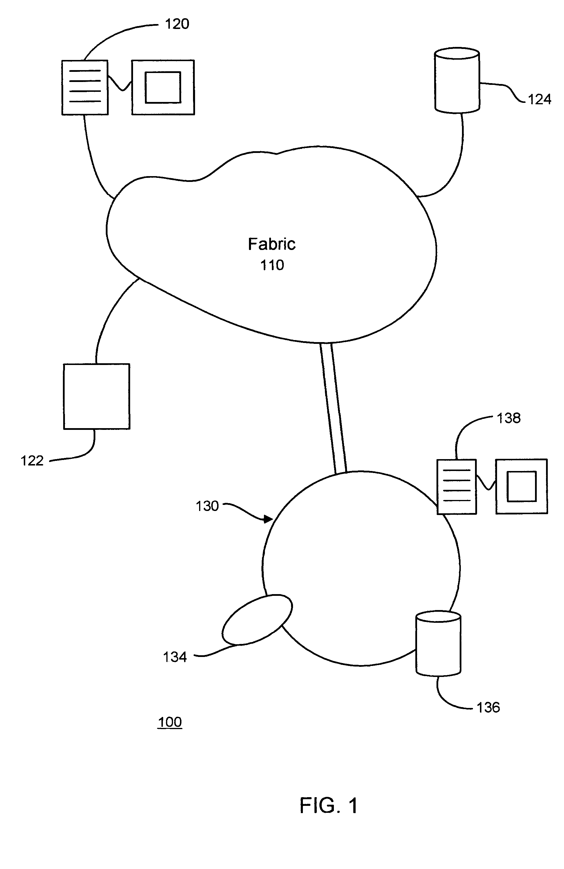
[0020]However, embodiment 100 further comprises a switch fabric 110 and a plurality of devices, such as 120, 122, 124, and / or groups of devices, such as 134, 136, and 138, as indicated with respect to logical loop 130, for example. In general, a switch fabric, such as fabric 110, may be communicatively coupled to various devices, such as, here, 120, 122, and 124, and may operate as a switching network to allow these devices to communicate with each other. Devices 120, 122, and 124 may comprise any type of device, such as, for example, a computing platform, a storage device, and / or the like, and are typically communicatively coupled via fabric 110 by employing point-to-point communications technology or techniques. In this particular embodiment fabric 110 is also in communication with logical loop 130. Loop 130 here includes devices 134, 136 and 138. In this particular embodiment, loop 130 comprises an arbitrated loop with ring couplings for providing multiple nodes with the ability ...

embodiment 200

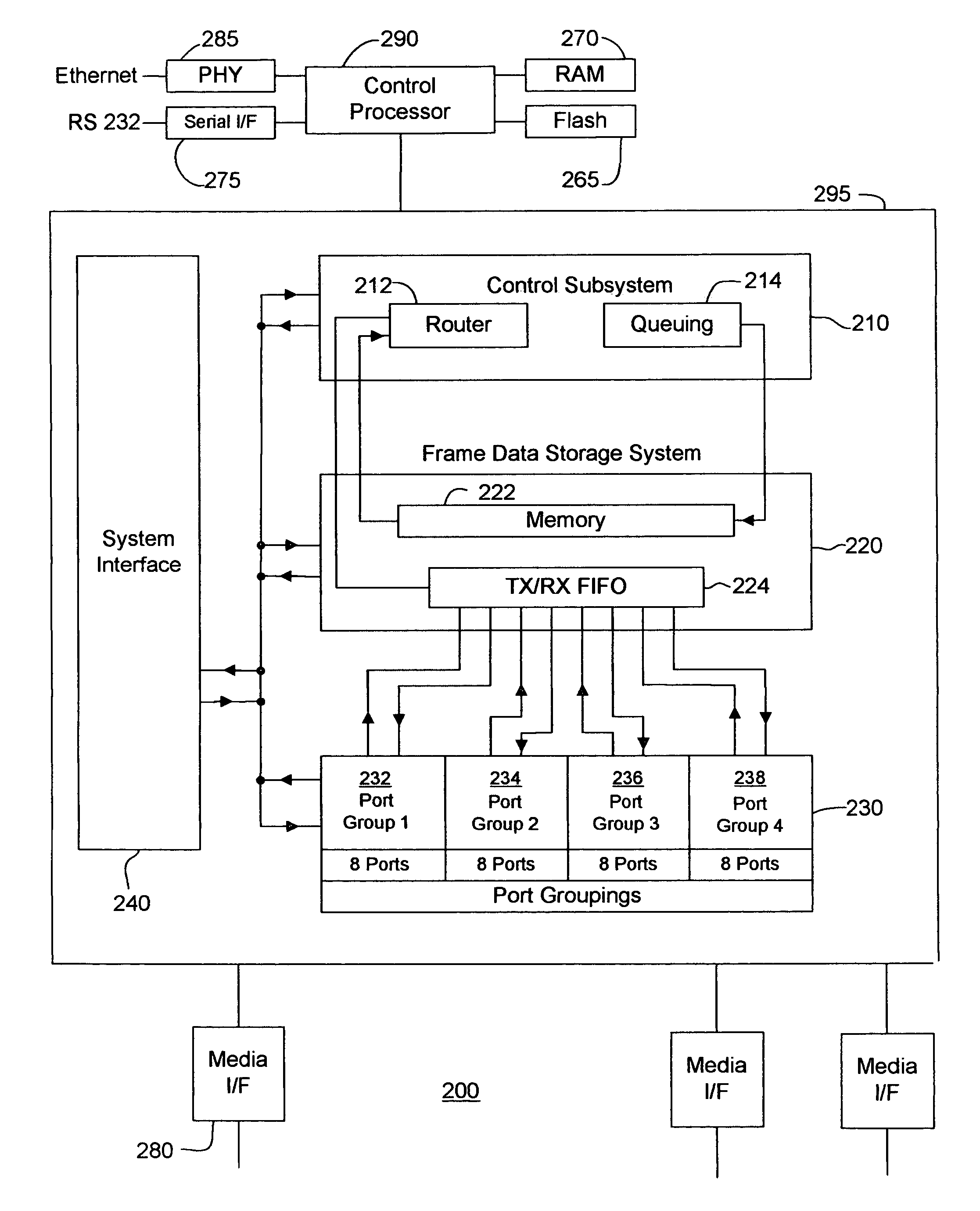
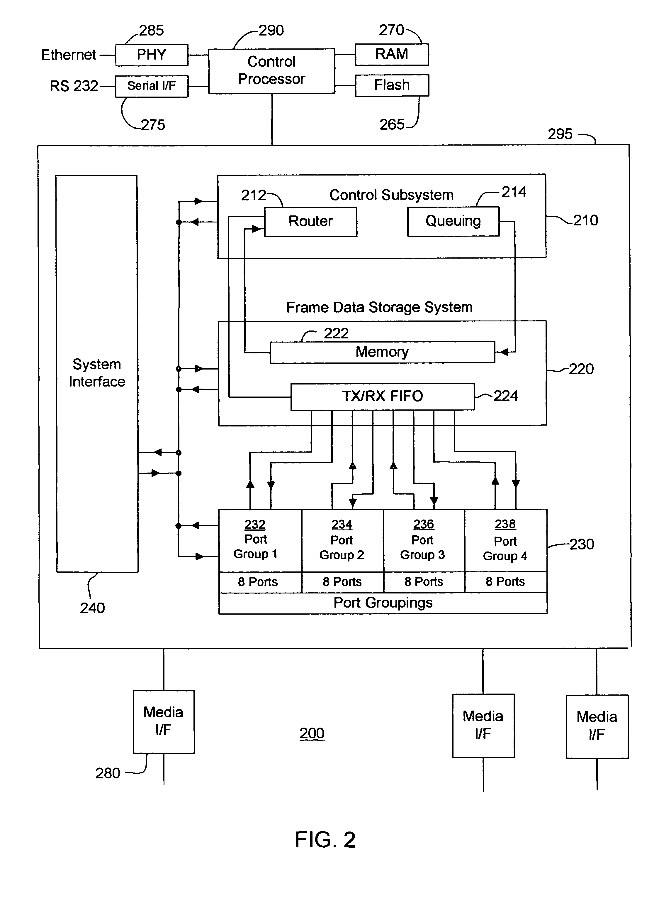
[0023]Although the claimed subject matter is not limited in scope to this embodiment, FIG. 2 illustrates an embodiment of a switch in accordance with the claimed subject matter. Embodiment 200 includes a control processor 290, an ASIC 295, a PHY 285, a media interface (I / F) 280, a serial interface 275, a RAM, 270 and flash memory 265, as well as other components. In this embodiment of a switch, the ASIC includes a control subsystem 210, a frame data storage system 220, port groupings 230, and an overall system interface 240. It is noted that FIG. 2 simply illustrates a potential architecture of a switch in accordance with the claimed subject matter. This architecture is provided only as an example and many other switch architectures are possible. The claimed subject matter is not limited to this or to any other particular architecture. This particular architecture offers versatility in some respects and may be employed in a variety of system configurations including a switch fabric ...


PUM


Abstract

Embodiments of methods, apparatuses and / or systems for balancing flow across trunk groups are disclosed. For example, a method of routing a flow of frames may include receiving at least one frame; selecting an exit port of a switch for the at least one frame to exit based, at least in part, on balancing flow across trunk groups; and transmitting the at least one frame.

Description

CROSS REFERENCE TO RELATED APPLICATIONS[0001]This patent application is related to concurrently filed patent applications, “Logical Ports in Trunking,” by Surya Varanasi, filed on Oct. 31, 2003, U.S. patent application Ser. No. 10 / 699,567; and “Load Balancing in Core-edge Configurations,” by Surya Varanasi filed on Oct. 31, 2003, U.S. patent application Ser. No. 10 / 699,568, both of the foregoing assigned to the assignee of the presently claimed subject matter and herein incorporated by reference.BACKGROUND[0002]1. Field[0003]This application relates generally to networking and, more particularly, to routing data traffic within a communications networking system.[0004]2. Background Information[0005]As used herein, the term “Fibre Channel” refers to the Fibre Channel family of standards (hereinafter referred to as “Fibre Channel”) developed by the American National Standards Institute (ANSI). In general, Fibre Channel defines a transmission media based at least in part on high speed c...

Claims


Application Information

Patent Timeline
Patent Type & Authority Patents(United States)
IPC IPC(8): G01R31/08H04J1/16H04L12/26H04J14/00H04L12/56
CPCH04L45/245H04L47/125H04L47/10Y02B60/33Y02D30/50
Inventor VARANASI, SURYAKO, KUNG-LING
Owner AVAGO TECH INT SALES PTE LTD
Learn More