Target orientation estimation using depth sensing

a depth sensing and target orientation technology, applied in the field of computer-based estimation of target orientation or pose, can solve problems such as failure of classification, selection of a set of features in a human face, and problems such as appearance-based classification

Active Publication Date: 2009-11-17
HONDA MOTOR CO LTD +1
View PDF32 Cites 422 Cited by
  • Summary
  • Abstract
  • Description
  • Claims
  • Application Information

AI Technical Summary

Problems solved by technology

There are always some instances where classification fails, primarily related to appearance variation.
The physical differences in appearance between the model and the target present a problem for appearance-based classification.
Particularly, in human face classifiers, selecting a set of features in a human face that can be tracked across all poses, between frames, and across a variety of target human faces presents a challenging problem.
It is difficult to define a “common appearance” that applies to everybody.
Appearance variation can be a problem even when operating on the same subject.
In addition, lighting conditions negatively impact the classification performance.
Therefore, appearance-based orientation estimation systems that operate based on generic model databases can typically only achieve limited recognition performance.
The great appearance variation between model and targets, or even between the same target at different times leads to unstable results.
This identification of particular features in an image is a hard problem on its own right.
These techniques suffer from several critical problems.
For instance, automatic model pose initialization is still a difficult problem.
Another drawback of motion estimation techniques is that the angle estimate is accurate only for a relatively short image sequence because error accumulation due to the incremental nature of the angle computation becomes too large for a long sequence.

Method used


Image

  • Target orientation estimation using depth sensing
  • Target orientation estimation using depth sensing
  • Target orientation estimation using depth sensing

Examples


Embodiment Construction

[0036]The Figures and the following description relate to preferred embodiments of the present invention by way of illustration only. It should be noted that from the following discussion, alternative embodiments of the structures and methods disclosed herein will be readily recognized as viable alternatives that may be employed without departing from the principles of the claimed invention.

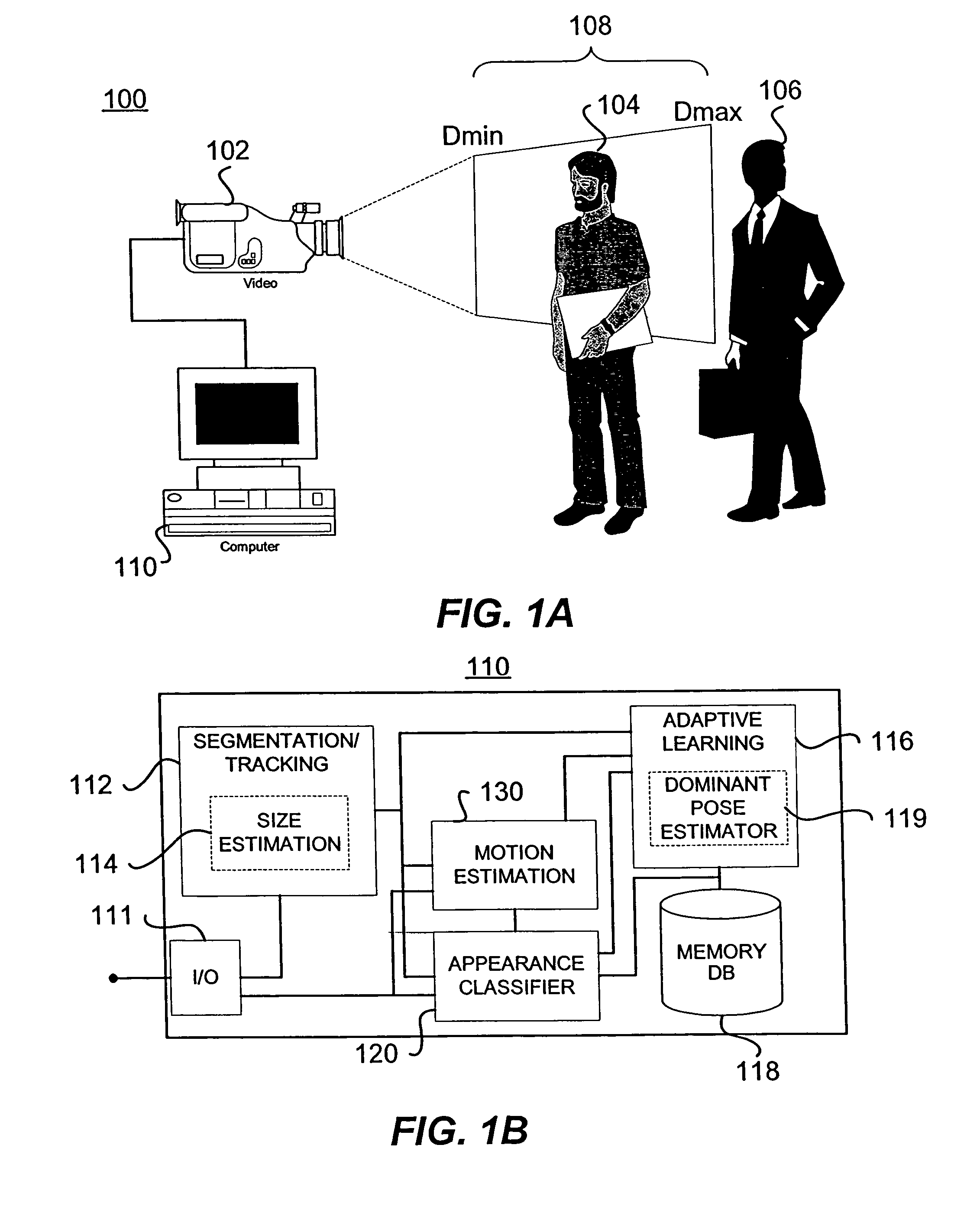
[0037]Referring now to FIG. (“FIG.”) 1A, one embodiment of an orientation estimation system configuration is shown. The orientation estimation system 100 in this embodiment uses depth-sensing technology. Depth-sensing technology is based on the time-of-flight principle. Cameras using this technology are known as time-of-flight cameras. In the present embodiment, the image capturing method of camera 102 is based on active sensing with a time-of-flight camera. Active depth sensing is performed with a pulse of infrared illumination. The pulse is projected to the target 104 and the sensor reads its e...


PUM


Abstract

A system for estimating orientation of a target based on real-time video data uses depth data included in the video to determine the estimated orientation. The system includes a time-of-flight camera capable of depth sensing within a depth window. The camera outputs hybrid image data (color and depth). Segmentation is performed to determine the location of the target within the image. Tracking is used to follow the target location from frame to frame. During a training mode, a target-specific training image set is collected with a corresponding orientation associated with each frame. During an estimation mode, a classifier compares new images with the stored training set to determine an estimated orientation. A motion estimation approach uses an accumulated rotation / translation parameter calculation based on optical flow and depth constrains. The parameters are reset to a reference value each time the image corresponds to a dominant orientation.

Description

RELATED APPLICATIONS[0001]This application is related to and claims priority from U.S. Provisional Patent Application Ser. No. 60 / 478,211 titled “Adaptive Face Pose Learning Using Depth Sensing” and filed on Jun. 12, 2003 by the same inventors, which is incorporated herein by reference in its entirety. This application is also related to co-pending U.S. patent application Ser. No. 10 / 875,581 filed on May 28, 2004 entitled “Visual Tracking Using Depth Data” by Fujimura, et al., which is incorporated herein by reference in its entirety.FIELD OF THE INVENTION[0002]The present invention relates generally to real-time computer vision and more particularly to computer based estimation of target orientation or pose.BACKGROUND OF THE INVENTION[0003]Pose estimation is a key component for many areas of real-time computer vision such as Human-Computer Interaction. For example, work has been done for driver monitoring to determine head pose using various facial cues to derive related attentiven...

Claims


Application Information

Patent Timeline
Patent Type & Authority Patents(United States)
IPC IPC(8): G06K9/00H04N5/225G02BG06T1/00G06V10/24
CPCG06K9/00201G06K9/00228G06K9/00241G06T7/0044G06K9/6203G06K9/6214G06K9/32G06T7/74G06F3/012G06T2200/04G06T2207/10028G08B21/06G06T2207/30201G06V40/164G06V20/64G06V40/161G06V20/597G06V10/24G06V10/76G06V10/7515G06T7/73G06T7/50
Inventor FUJIMURA, KIKUOZHU, YOUDING
Owner HONDA MOTOR CO LTD
Why Eureka
Try Eureka