Elevator with vertical vibration compensation

a technology of vertical vibration compensation and elevator, which is applied in the field of elevators, can solve the problems of low frequency deterioration of perceived ride quality, and undermining passenger confidence, and achieve the effect of reducing vertical vibration of elevator cars

Active Publication Date: 2009-11-24
INVENTIO AG
View PDF24 Cites 18 Cited by
  • Summary
  • Abstract
  • Description
  • Claims
  • Application Information

AI Technical Summary

Benefits of technology

[0010]Accordingly, an objective of the present invention is to reduce vertical vibrations of an elevator car.
[0012]Furthermore, provided that the auxiliary motor has sufficient power, when the car is stationary at a landing, the auxiliary motor can keep the car level with the landing and therefore the conventional re-leveling operation executed by the main drive is no longer required.
[0014]Advantageously the error signal is fed into an auxiliary controller which outputs a force command signal to a power amplifier providing energy to the auxiliary motor. The auxiliary controller provides the necessary conditioning of the error signal to ensure effective vibration damping. The auxiliary controller may comprise a band-pass filter to suppress components of the signal having a frequency less than the fundamental frequency of the elevator to prevent any build up of steady state errors. The upper cut-off frequency of the filter can be determined by the dynamics of the control system so as to prevent high frequency jitter. Furthermore the auxiliary controller preferably contains a proportional amplifier to produce a behavior commonly known as skyhook damping. Additionally, the auxiliary controller may also comprise a differential amplifier, an integral amplifier and / or a double integral amplifier to add virtual mass to the car and virtual stiffness to the system.
[0015]Preferably the car is guided along the guide rails by roller guides, each roller guide comprising a plurality of wheels engaging with the guide rail and wherein the auxiliary motor is arranged to rotate at least one of the wheels. Many elevators already use roller guides to guide the car along the guide rails and driving one of the wheels of the roller guides with the auxiliary motor is an efficient, relatively low-cost and lightweight way of implementing the present invention.
[0016]Preferably a shaft of the driven wheel is rotatably mounted at a first point of a lever which is pivotably secured to the car at a second point and a shaft of the of the auxiliary motor is aligned with the second point with a transmission belt arranged around the shaft of the driven wheel and the auxiliary motor ensuring simultaneous rotation. With this arrangement the auxiliary motor is in a fixed position with respect to the car and accordingly the motor is not required to move with the wheel which can be subject to vibration.
[0017]In order to reduce the energy demand of the system, the auxiliary motor is preferably of a synchronous, permanent magnet type so that energy can be regenerated when the motor is decelerating the car and working as a generator and not as a motor. Ultracapacitors can be incorporated in the power amplifier to store this recovered energy for subsequent use.

Problems solved by technology

A common problem associated with most elevators is that of low frequency vertical vibration of the elevator car.
Vibrations at such low frequencies are easily perceptible to passengers, undermining passenger confidence in the safety of the elevator and generally leading to deterioration in perceived ride quality.
a) those due to fluctuations in the load of the car caused by embarkation and disembarkation of passengers while the car is held stationary by the drive at a landing; and
b) vibrations during travel caused by car overshoot during jerk phases of the drive, interference with other components within the elevator hoistway (wind forces due to passage of the car past shaft doors and neighboring cars within the hoistway, counterweight crossing, etc.) and movement of passengers within the traveling car.
However, this solution is only applicable to a stationary elevator car and cannot solve the vibration experienced by a passenger in a traveling elevator car.
The use of the main drive in this fashion, particularly since the car and landing doors are open, obviously presents an unwanted safety risk to passengers.
The steady-state displacement must be determined before the re-leveling operation can commence, hence it necessarily has a slow reaction time.
Furthermore, the re-leveling operation itself excites further low frequency vibrations.
However, this compensation of the response always increases travel time and therefore reduces the transport capacity of the elevator.
Furthermore, such compensation cannot solve the problem of vibrations induced by interference of the traveling car with other components within the elevator hoistway and movement of passengers within the car.
This increase in elasticity combined with the decrease in the fundamental frequency makes the car much more susceptible to low frequency vertical vibrations.

Method used


Image

  • Elevator with vertical vibration compensation
  • Elevator with vertical vibration compensation
  • Elevator with vertical vibration compensation

Examples


Embodiment Construction

[0029]To avoid unnecessary repetition within the description, features that are common to more than one embodiment have been designated with the same reference numerals.

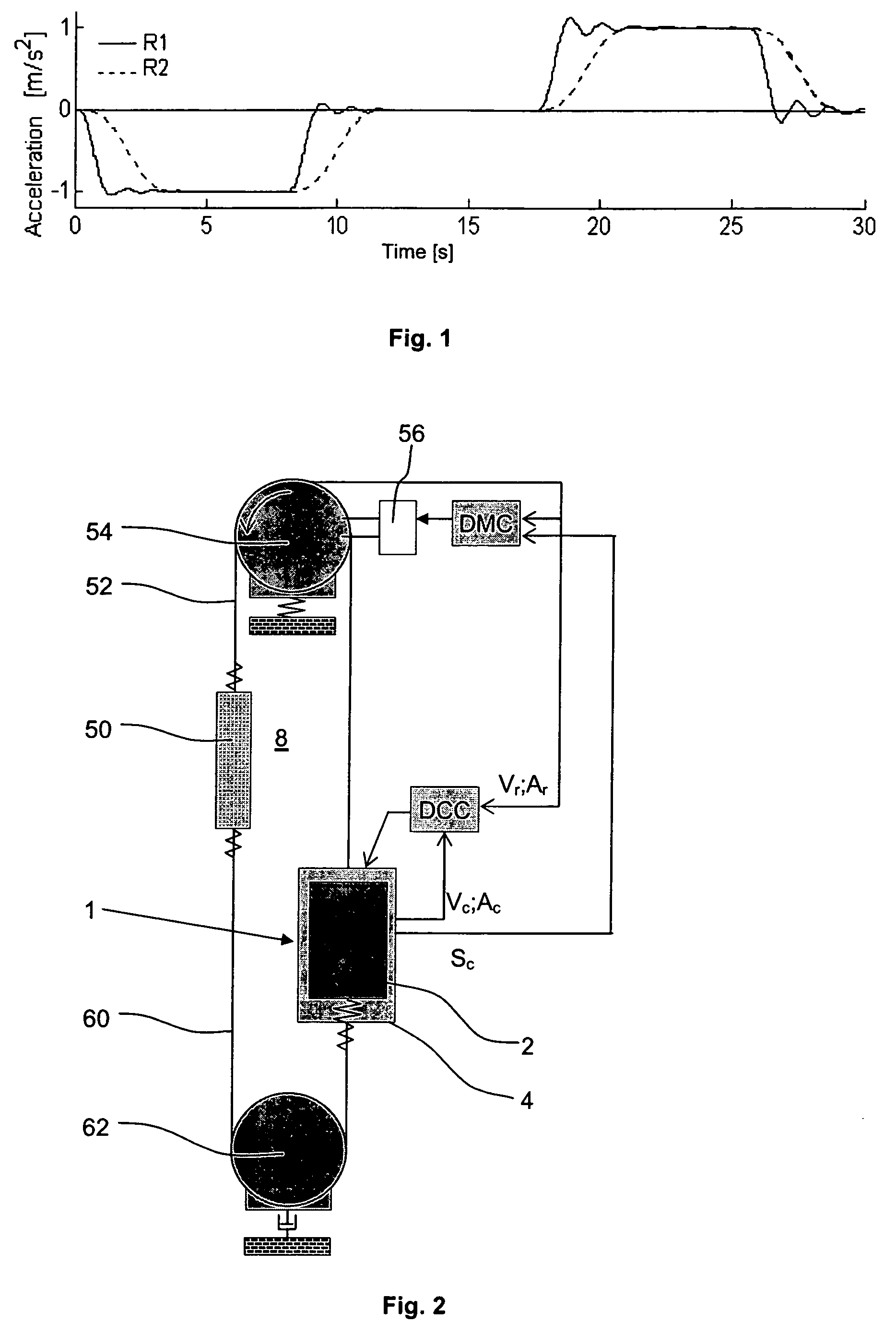
[0030]FIG. 2 illustrates an elevator according to the present invention. The elevator includes an elevator car 1 which is arranged to travel upwards and downwards within a hoistway 8 of a building. The elevator car 1 comprises a passenger cabin 2 supported in a frame 4. A traction rope 52 interconnects the car 1 with a counterweight 50 and this rope 52 is driven by a traction sheave 54 located above or in an upper region of the hoistway 8. The traction sheave 54 is mechanically coupled to a main motor 56 which is controlled by an elevator controller DMC. The traction rope 52, the traction sheave 54, the motor 56 and the elevator controller DMC constitute the main drive used to support and propel the car 1 though the hoistway 8. In high-rise elevators the weight of the traction rope 52 is significant and a compensatio...


PUM


Abstract

An elevator has a car traveling along guide rails within a hoistway and a main drive propelling the car. A sensor mounted on the car measures a vertical travel parameter of the car, a comparator compares the sensed car travel parameter with a reference value derived from the main drive, and an auxiliary motor mounted on the car exerts a vertical force on at least one of the guide rails in response to an error signal output from the comparator.

Description

BACKGROUND OF THE INVENTION[0001]The present invention relates to elevators and, in particular, to a device for reducing transient vertical vibration acting on an elevator car.[0002]A common problem associated with most elevators is that of low frequency vertical vibration of the elevator car. This phenomenon is principally due to the inherent elasticity of the main drive system used to propel and support the car within the hoistway; for example the compressibility of the working fluid used in hydraulic elevators and the elasticity of the rope used in traction elevators. Accordingly, any fluctuation in the force acting on the car will cause transient vertical vibration about a steady-state displacement of the car. The predominant frequency of these vibrations is that of the fundamental mode of vibration which is dependent on the travel height of the elevator and, for a traction elevator, the type of rope used. For a traction elevator having a travel path of 400 m and using steel rop...

Claims


Application Information

Patent Timeline
Patent Type & Authority Patents(United States)
IPC IPC(8): B66B1/34
CPCB66B7/042B66B11/0266B66B7/046
Inventor HUSMANN, JOSEF
Owner INVENTIO AG
Why Eureka
Try Eureka