
Belt grinding machine with a belt adjusting device

a belt grinding machine and belt technology, applied in the field of belt grinding machines with belt adjusting devices, can solve problems such as belt deviation, and achieve the effect of improving the safety and convenience of operation and adjustmen

Inactive Publication Date: 2009-11-24
J&T MACHINERY
View PDF4 Cites 9 Cited by
  • Summary
  • Abstract
  • Description
  • Claims
  • Application Information

AI Technical Summary

Benefits of technology

[0011]The primary objective of the present invention is to provide a belt grinding machine with a belt adjusting device which can adjust rollers and a belt of the belt grinding machine simply by rotating a screw that is exposed out of an outer cover, and can improve the safety and convenience of operation and adjustment.
[0012]The second objective of the present invention is to provide a belt grinding machine with a belt adjusting device which can further improve the safety of the belt grinding machine. When the outer cover is open, it will press an emergency switch of the housing and consequently cut off the power supply.
[0014]Moreover, the housing is provided with an emergency switch, when the outer cover is open, it will press the emergency switch of the housing and consequently cut off the power supply and stop the motor, so as to prevent injury to the user caused by accidentally touching the switch and starting the belt grinding machine when the outer cover is opened.

Problems solved by technology

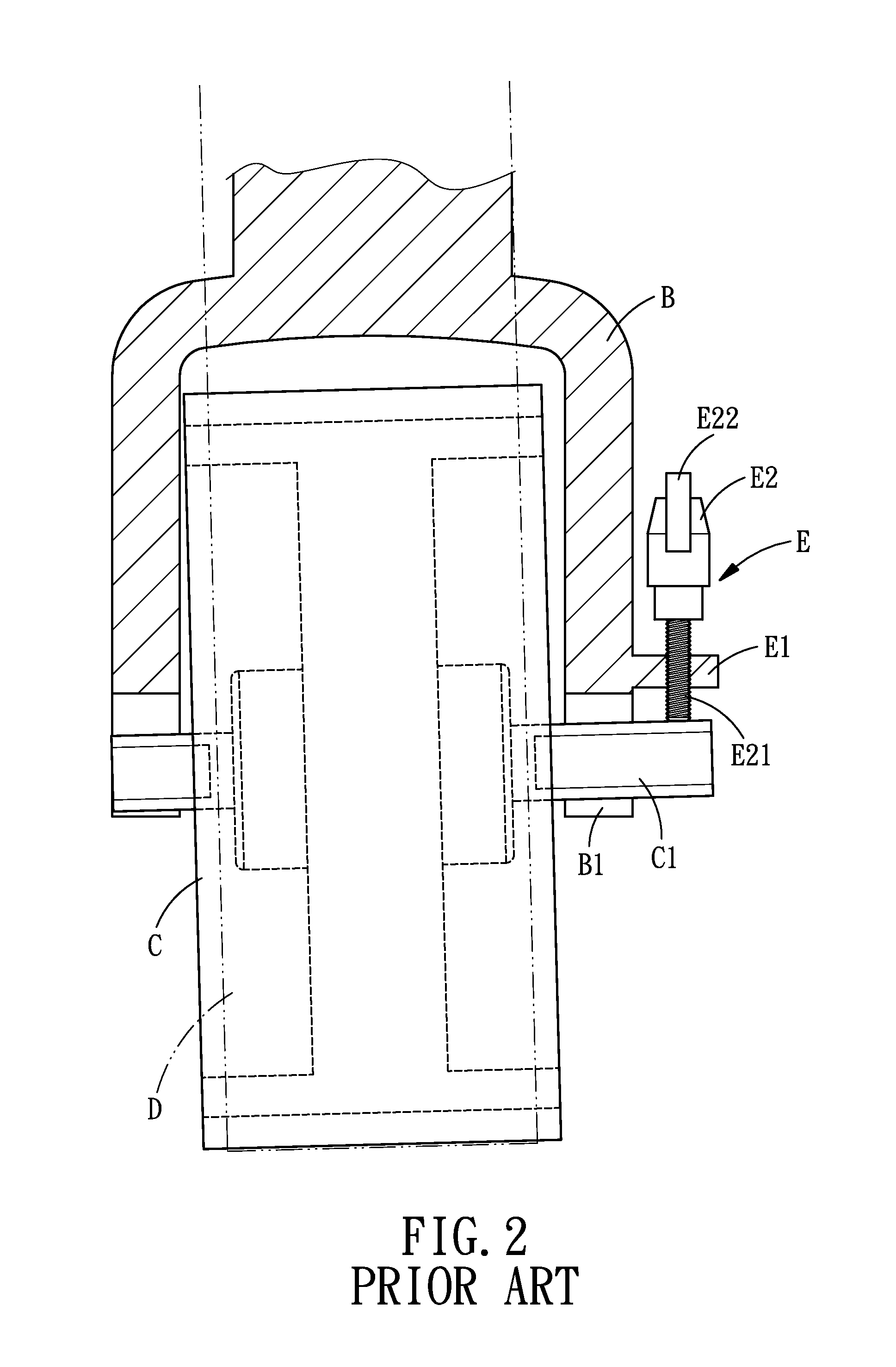
The problem is that the belt grinding machine is driven by motor, which inevitably will cause vibration during operation, on top of that, various kinds of external conditions, such as the influence of tension of the belt, will cause displacement of the rotating shafts and make them unparallel, resulting in the deviation of the belt.
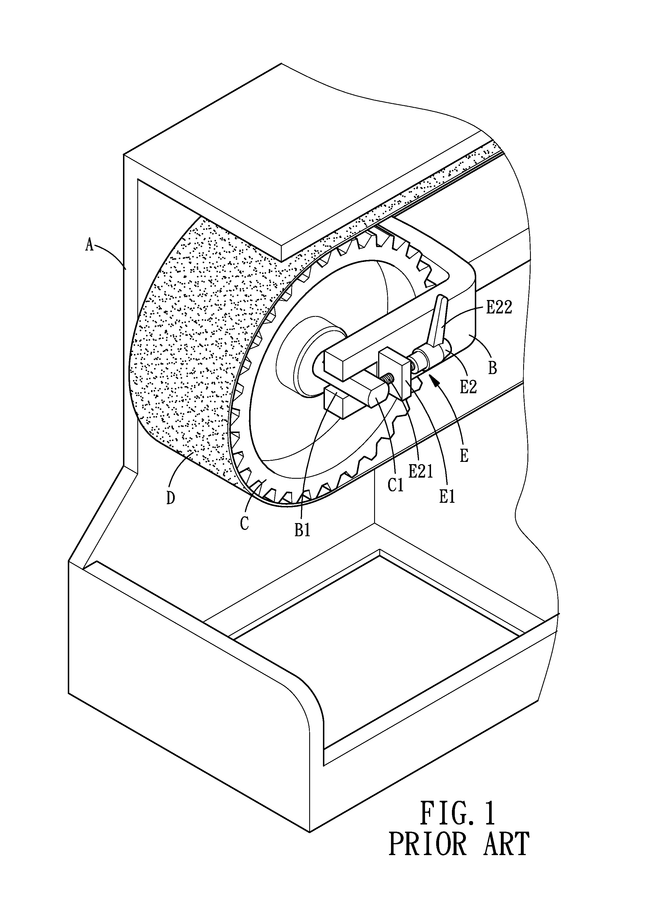
Referring to FIGS. 1-3 again, during the adjustment operation, since the conventional mechanism is not provided with an outer cover for the sake of adjustment, the worker is likely to be caught by the roller C or the belt D by accidentally touching them at a high speed rotation, causing injury.

Method used


Image

  • Belt grinding machine with a belt adjusting device
  • Belt grinding machine with a belt adjusting device
  • Belt grinding machine with a belt adjusting device

Examples


Embodiment Construction

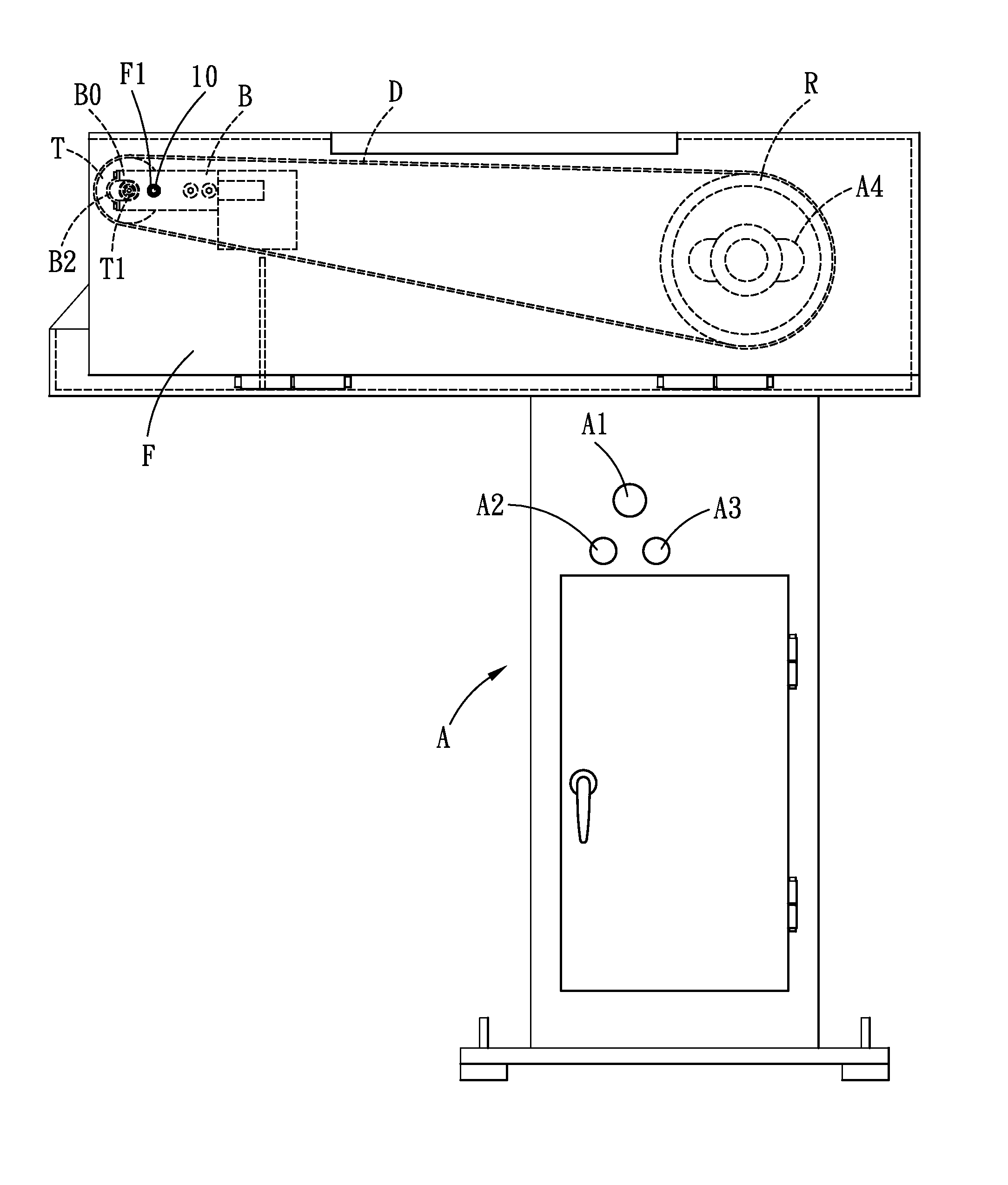
[0028]Referring to FIGS. 4-9, a belt grinding machine with a belt adjusting device in accordance with the present invention comprises a housing A, a motor M, a drive roller R, two supporting racks B, a driven roller T, a belt D, an outer cover F and an adjusting device O.

[0029]The housing A is provided with an emergency switch A1, a start switch A2 and a stop switch A3. One side of the housing A is an open side.

[0030]The motor M is disposed at the other side of the housing A and is to be started and stopped by the start switch A2 and the stop switch A3, respectively. The housing A is defined with an elongated through hole A4 for insertion of a shaft M1 of the motor M. In the present embodiment, the housing A is provided with a carrying platform A5, and two guide rails A6 and a bearing A7 are disposed on the carrying platform A5. At a bottom of the motor M is provided a slide table M2. At a bottom of the slide table M2 is provided two sliding blocks M3 and a driving block M4, and the...


PUM


Abstract

A belt grinding machine with a belt adjusting device utilizes a screw to radially push an inclined surface of a push rod to make the push rod move axially to push rollers of the belt grinding machine, and thus the belt winding around the rollers can be adjusted. In an outer cover of the belt grinding machine is defined a penetrating hole for allowing a screw to extend out therethrough, so as to improve the safety and convenience of operation and adjustment. Moreover, the belt grinding machine is provided with an emergency switch located correspondingly to the outer cover, when the outer cover is open, it will press the emergency switch of the housing and consequently cut off the power supply, so as to further improve the safety of the belt grinding machine.

Description

BACKGROUND OF THE INVENTION[0001]1. Field of the Invention[0002]The present invention relates to a machine tool using a polishing belt, and more particularly to a belt grinding machine with a belt adjusting device.[0003]2. Description of the Prior Art[0004]Sand paper is the simplest, the most common and useful tool for grinding and polishing, however, in the past, the user always utilizes the sand paper to perform a grinding operation by hands directly, therefore, the planeness of the object to be ground is more likely to be influenced by the skill of the user, or even the goods will be deformed by overgrinding, for example, a surface which is expected to be a flat surface is finally ground into an arc-shaped surface.[0005]Therefore, an electric grinding tool, such as, a grinding wheel machine and a belt grinding machine, is developed. The belt grinding machine comprises a grinding belt winding around two rollers and a motor for driving one of the rollers to rotate, and then the gri...

Claims


Application Information

Patent Timeline
IPC IPC(8): B24B23/06
CPCB24B21/20
Inventor LIAO, HSIU-CHING
Owner J&T MACHINERY
Learn More