
Adaptor for cable connector

a technology for adapters and connectors, which is applied in the direction of coupling contact members, coupling device connections, coupling parts, etc., can solve the problems of peeled cables from reinforcing plates in some cases, and achieve the effect of convenient mounting or dismounting

Active Publication Date: 2009-12-01
YAMAICHI ELECTRONICS
View PDF72 Cites 18 Cited by
  • Summary
  • Abstract
  • Description
  • Claims
  • Application Information

AI Technical Summary

Benefits of technology

The invention provides an adaptor for a cable connector that securely connects a cable to a receptacle. The adaptor has a protection portion and a connection portion that form a stationary surface for securing the cable end portion. The adaptor also has a lock spring receiving portion for receiving a lock spring and a vertical slit for communicating the lock spring to the outside. The connection portion and the reinforcing portion are formed in parallel to each other, preventing the cable from being peeled off. The adaptor is easy to mount on or dismount from the receptacle and securely makes the electrical connection.

Problems solved by technology

Accordingly, even with the flexible cable, if a torque such as twist is applied to the flexible cable, there is risk that the cable is peeled from the reinforcing plate in some cases.

Method used


Image

  • Adaptor for cable connector
  • Adaptor for cable connector
  • Adaptor for cable connector

Examples


Embodiment Construction

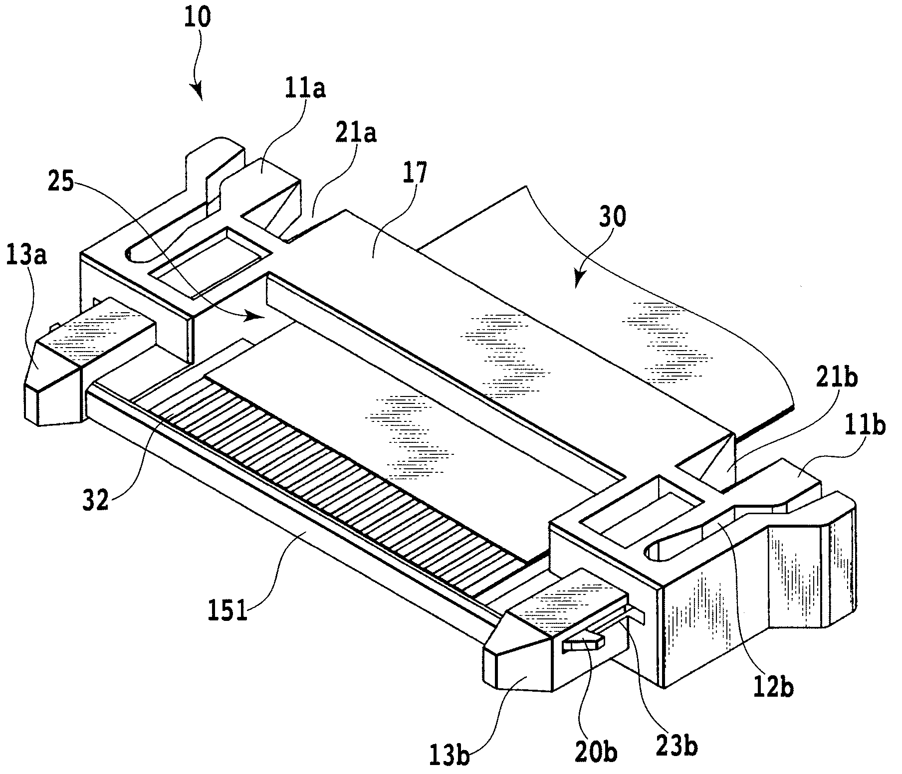
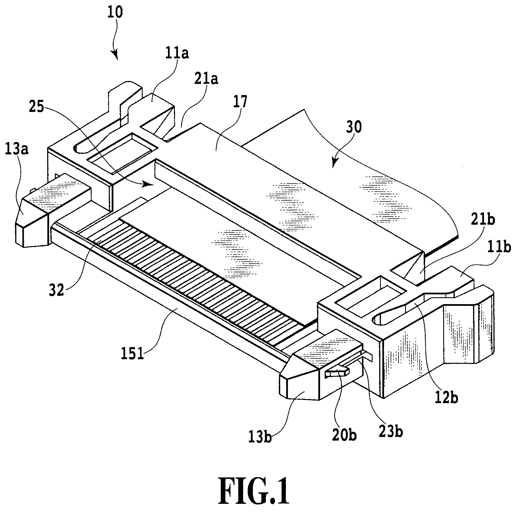
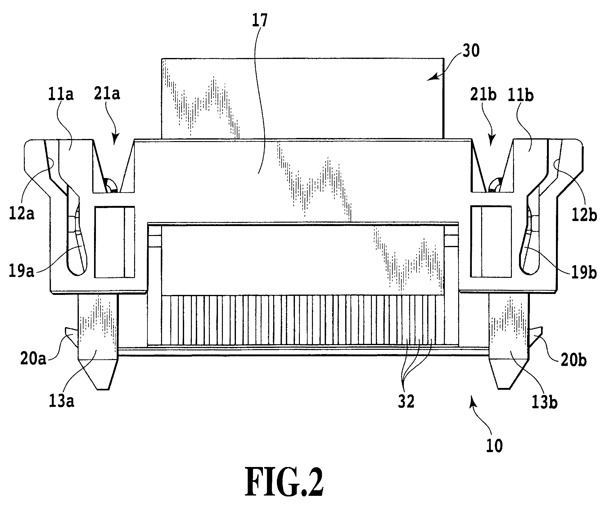
[0029]Referring to FIGS. 1 to 11, the preferred embodiments of an adaptor for a cable connector according to the present invention will be described below.

[0030]FIG. 1 is a perspective view of the adaptor for the cable connector according to the invention, as seen from the lower, obliquely front side. FIG. 2 is a lower view of the adaptor for the cable connector of FIG. 1. FIG. 3 is a front view of the adaptor for the cable connector of FIG. 1. FIG. 4 is a cross-sectional view taken along the line IV-IV in FIG. 3. FIG. 5 is a perspective view of a receptacle as a female connector with which the adaptor for the cable connector of FIG. 1 is removably connected, as seen from the upper, obliquely front side. FIG. 6 is a perspective view showing a state where the adaptor for the cable connector of FIG. 1 is connected with the receptacle provided on a printed circuit board, as seen from the upper, obliquely front side. FIG. 7 is a cross-sectional view taken along the line VII-VII in FIG. ...


PUM


Abstract

An adapter for a cable connector secured with a cable end portion to make the electrical connection by being removably mounted on a receptacle of the cable connector includes a pair of operation portions, a pair of guide pins integrally formed in front of the operation portions and each having a pointed end portion at the front, a protection portion for connecting the operation portions at the rear lower part, a connection portion for connecting the operation portions at the front upper part, and a reinforcing portion for connecting the pair of guide pins, wherein the protection portion and the connection portion have an interval in the longitudinal and vertical directions and are disposed in parallel to each other, and the lower surfaces of the connection portion and the reinforcing portion are continuous flush to form a stationary surface for securing the cable end portion.

Description

[0001]This application claims the benefit of Japanese Patent Application Nos. 2007-172680, filed Jun. 29, 2007 and 2008-114429, filed Apr. 24, 2008 which are hereby incorporated by reference herein in their entirety.BACKGROUND OF THE INVENTION[0002]1. Field of the Invention[0003]The present invention relates to an adapter for a cable connector for electrically connecting one end of a flexible and flat cable such as a flexible flat cable or a flexible printed wiring board to the cable connector provided on a wiring board.[0004]2. Description of the Related Art[0005]A cable connector is practically employed in making the electrical connection between electric components inside an electronic apparatus. The cable connector has a connection structure of a cable for electrically connecting an electric component or a printed wiring board (PB) for an electronic apparatus via a flexible cable such as a flexible flat cable (FFC) or a flexible printed circuit board (FPC), for example.[0006]Suc...

Claims


Application Information

Patent Timeline
Patent Type & Authority Patents(United States)
IPC IPC(8): H01R12/24
CPCH01R12/79H01R13/6275H01R12/725
Inventor TAKAHIRA, HIROSHI
Owner YAMAICHI ELECTRONICS
Learn More