Clip for clamping cloth for use with embroidery frame

a cloth and embroidery frame technology, applied in the direction of snap fasteners, buckles, automatic machines, etc., can solve the problems of poor outer appearance, insufficient clamping of straight parts of the outer frame, and inability to clamp the straight parts of the inner frame. , to achieve the effect of easy mounting or dismounting, low cost, and not reducing the range of embroidery sewing

Active Publication Date: 2008-09-02
BROTHER KOGYO KK
View PDF19 Cites 5 Cited by
  • Summary
  • Abstract
  • Description
  • Claims
  • Application Information

AI Technical Summary

Benefits of technology

[0009]An object of the invention is to provide a clip for clamping a cloth which is compact and lightweight, and can be easily mounted or dismounted, and with which a reliable stretching and holding force can be obtained, and a sufficient range of embroidery sewing can be ensured.
[0011]According to such structure, because the leaf spring member is provided with the urging member for pressing a part of the cloth to be worked extending upwardly from between the outer frame and the inner frame, it is possible to reliably clamp the cloth to be worked by means of the clip for clamping the cloth, keeping the cloth in a stably held state, and to prevent a slack of the cloth to be worked on occasion of embroidery sewing.
[0012]Moreover, the first engaging portion and the second engaging portion of the leaf spring member are so designed as to be engaged with the outer frame, on occasion of mounting the clip for clamping the cloth on the embroidery frame. Accordingly, the clip can be made compact and lightweight, provided that the clip has such a size as can be mounted on the outer frame, and therefore, the clip can be produced at low cost and can be also applied to an embroidery frame of a sewing machine for home use. Because the clip for clamping the cloth is intended for use mounted on the outer frame, the clip will not project into the inner frame, and will not decrease the range of the embroidery sewing. Also, in case of stretching again the cloth to be worked, the clip can be easily mounted or dismounted.

Problems solved by technology

Specifically, even though the outer frame is clamped onto the inner frame by means of the clamping mechanisms, the straight parts of the outer frame is not able to be sufficiently clamped onto the straight parts of the inner frame, because the respective straight parts of the outer frame and the inner frame have long lengths.
Therefore, in case of conducting embroidery sewing for example on a thin cloth, particularly the straight parts of the frames cannot be sufficiently clamped.
Consequently, an embroidery pattern may become smaller than desired, and contorted, or wrinkles may occur around the embroidery pattern, resulting in a poor outer appearance.
Accordingly, there has been such anxiety that the clip which is clamping the cloth to be worked may be displaced with vibrations or so, on occasion of conducting the embroidery sewing, and the cloth may become slackened.
In order to correct the slack, the inner frame together with the clip must be dismounted from the outer frame, but it is not easy to mount or dismount the clip.
Further, in order to obtain a sufficient stretching and holding force of the locking clip, it is necessary to make both a diameter of the engaging pipe and a diameter of the locking clip larger, and consequently, the engaging pipe will undesirably protrude upwardly.
For this reason, this locking clip cannot be applied to a sewing machine intended for home use in which a space above the sewing machine cannot be sufficiently secured on occasion of conducting the embroidery sewing.

Method used


Image

  • Clip for clamping cloth for use with embroidery frame
  • Clip for clamping cloth for use with embroidery frame
  • Clip for clamping cloth for use with embroidery frame

Examples


first embodiment

[0031]Now, the invention will be described referring to FIGS. 1 to 8.

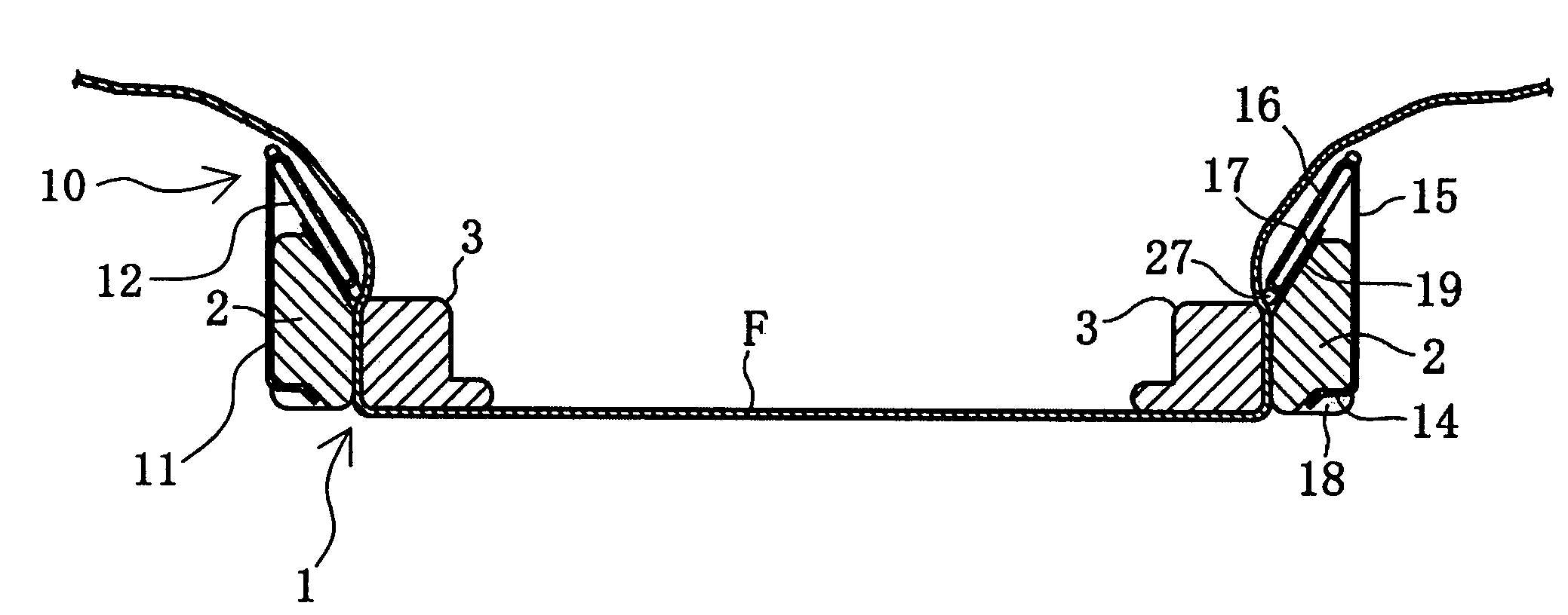
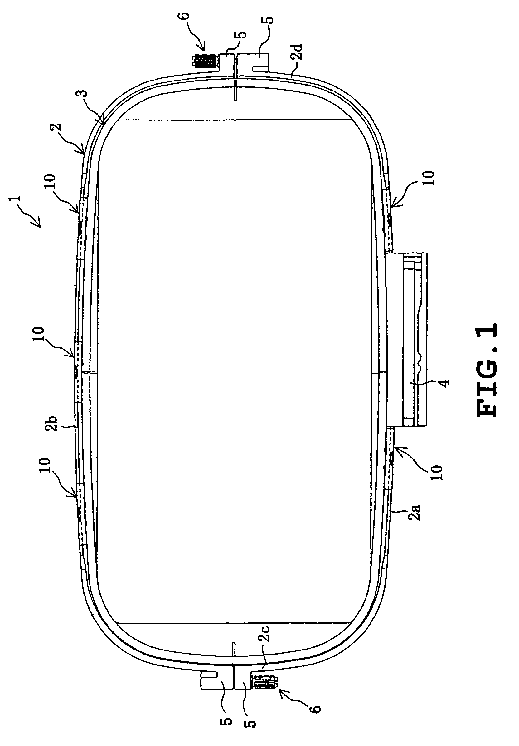
[0032]As shown in FIG. 1, an embroidery frame 1 has a substantially rectangular shape in a plan view, and includes an outer frame 2 and an inner frame 3. The outer frame 2 has four sides 2a to 2d in a substantially straight line, and its corner parts are rounded. The longer side 2a of the outer frame is provided with a fitting part 4 which is connected to a driving force outlet (not shown) of an embroidery frame moving mechanism (not shown) of an embroidering machine (not shown). A pair of the shorter sides 2c, 2d of the outer frame are respectively provided with clamped parts 5 which are divided at respective centers in a longitudinal direction thereof. Further, the sides 2c, 2d are respectively provided with clamping mechanisms 6 which are so constructed as to clamp the outer frame 2 onto the inner frame 3 by tightening the aforesaid clamped part 5.

[0033]The outer frame side 2b on an opposite side to the fitting ...


PUM

PropertyMeasurementUnit
acute angleaaaaaaaaaa
angleaaaaaaaaaa
angleaaaaaaaaaa

Abstract

A clip for clamping a cloth according to the invention is mounted on an embroidery frame including an outer frame, and an inner frame which is internally engaged with the outer frame thereby to hold a cloth to be worked between the outer frame and the inner frame. The clip includes a leaf spring member which can be detachably mounted on the outer frame, and an urging member which is fitted to this leaf spring member and adapted to press the cloth to be worked onto the inner frame. The leaf spring member has a first engaging portion adapted to be engaged with a lower part of the outer frame from outside, a first plate portion extending upwardly from the first engaging portion, a second plate portion formed in an upper part of this first plate portion by way of a bent portion and downwardly inclined along an inner face of the outer frame, and a second engaging portion formed in this second plate portion and adapted to be engaged with an upper part of the outer frame from inside. The urging member is provided on the second plate portion and adapted to press a part of the cloth to be worked extending upwardly from between the outer frame and inner frame onto the inner frame. According to the structure, the cloth to be worked can be reliably clamped to be held in a stabilized state, and a slack of the cloth while embroidering can be prevented. At the same time, the clip can be made compact and lightweight, and can be easily mounted or dismounted.

Description

BACKGROUND OF THE INVENTION[0001]1. Field of the Invention[0002]The present invention relates to a clip for clamping a cloth to be mounted on an embroidery frame which is used for conducting embroidery sewing on an embroidering machine, and more particularly, to the clip for clamping the cloth which is intended to increase a stretching and holding force with respect to a cloth to be worked which has been held on the embroidery frame in a stretched manner.[0003]2. Description of the Related Art[0004]As an example of an embroidery frame for holding a cloth to be worked in a stretched manner on occasion of conducting embroidery sewing on an embroidering machine, a structure which includes, for example, an outer frame having a pair of clamping mechanisms and an inner frame to be fitted to an inside of this outer frame has been known. The above described outer frame and inner frame are formed in a rectangular shape, respectively having corner parts and straight parts.[0005]In case of set...

Claims


Application Information

Patent Timeline
Patent Type & Authority Patents(United States)
IPC IPC(8): D05C1/04D05B39/00A44B99/00D05C9/04
CPCD05C9/04Y10T24/44034Y10T24/44Y10T24/44641Y10T24/44855
Inventor HORI, MASAYUKI
Owner BROTHER KOGYO KK
Why Eureka
Try Eureka