Starter arrangement for an internal combustion engine

a technology for starting devices and internal combustion engines, which is applied to engine starting devices, muscle operated starters, machines/engines, etc., can solve the problems of inability to engage, introduce new problems, and low cost of starting systems, and achieve the effect of convenient mounting and dismounting

Active Publication Date: 2009-06-18
VOLVO CAR CORP
View PDF7 Cites 7 Cited by
  • Summary
  • Abstract
  • Description
  • Claims
  • Application Information

AI Technical Summary

Benefits of technology

[0009]An object of the present invention is to provide an improved starter arrangement for an internal combustion engine, and a starter arrangement which is easily mounted and dismounted. The starter arrangement may include a starter motor having a pinion gear coupled to an output shaft, the pinion gear being arranged in constant engagement with a corresponding crank gear of a crank wheel located between an engine block and a flywheel of the engine. The crank wheel is operatively coupled to a crankshaft of the engine via a one-way clutch unit loosely fitted to an end of the crankshaft, the crankshaft including a circumferential slot carrying a clip ring. The one-way clutch unit including a tube shaped hub loosely fitted to an end of the crankshaft, the axial movement of the one-way hub is fixed via a clip-ring in co-operation with a first axially delimiting member and a second axially delimiting member at least partially enclosed by the hub.

Problems solved by technology

Starter based systems are low cost and scalable to all sizes and kinds of power-trains but have two major drawbacks.
On the one hand they cannot be engaged during engine ramp down and on the other hand they are quite noisy due to engagement noise and cranking noise.
Although JP 2002 74337 addresses the noise and engagement problems by the ring gear engaging and always meshing with the pinion gear a new problem is introduced.
This is likely to put considerable strain on the one-way clutch of the starter arrangement.
However, it has been found that in order to appropriately affix a hub of the one-way clutch to the crankshaft the hub may be press fitted thereupon using special tooling applying considerable force.
This makes it cumbersome to mount the one-way clutch, and certainly even more cumbersome to dismount and service the arrangement at an ordinary garage.

Method used


Image

  • Starter arrangement for an internal combustion engine
  • Starter arrangement for an internal combustion engine
  • Starter arrangement for an internal combustion engine

Examples


Embodiment Construction

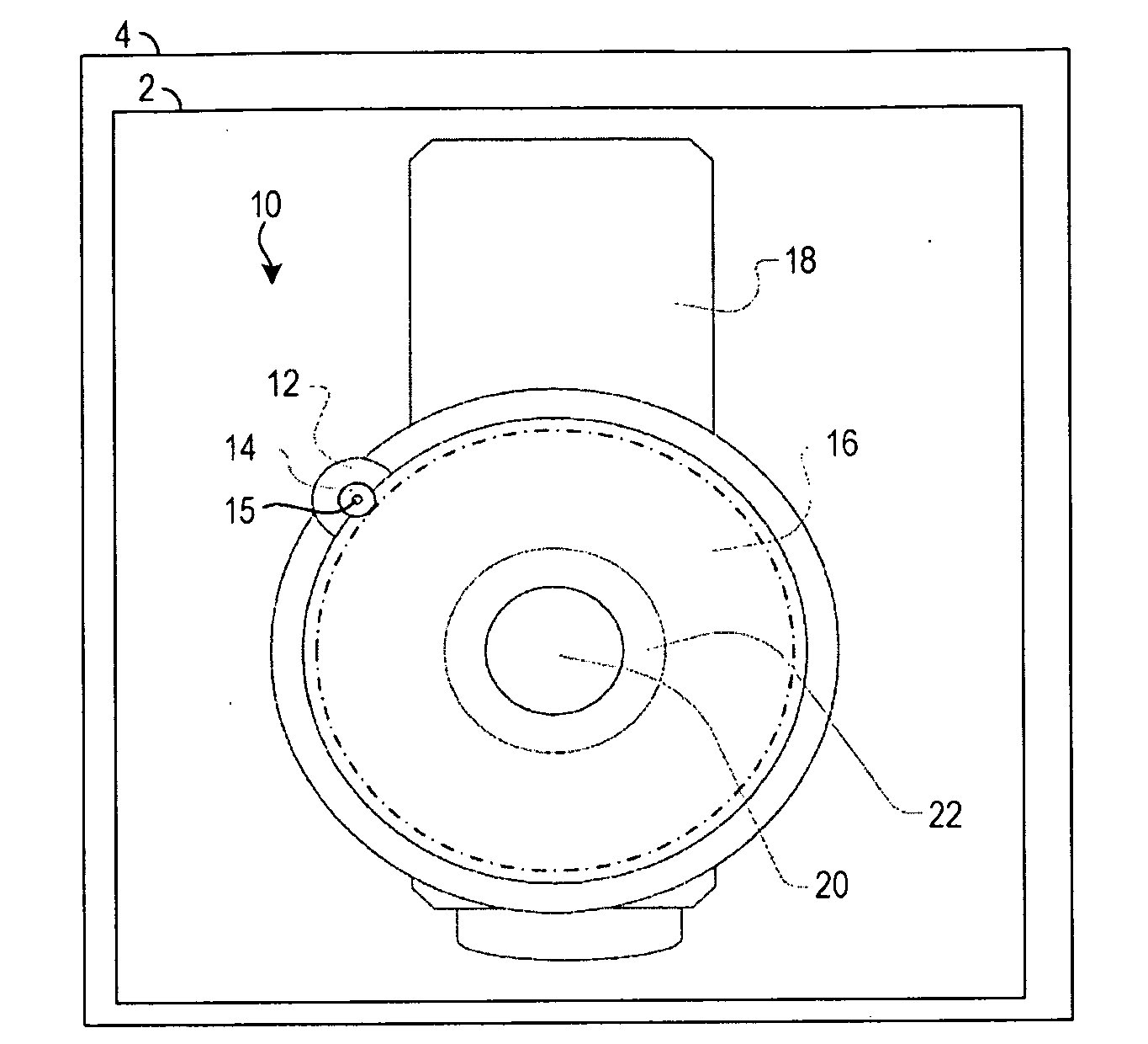
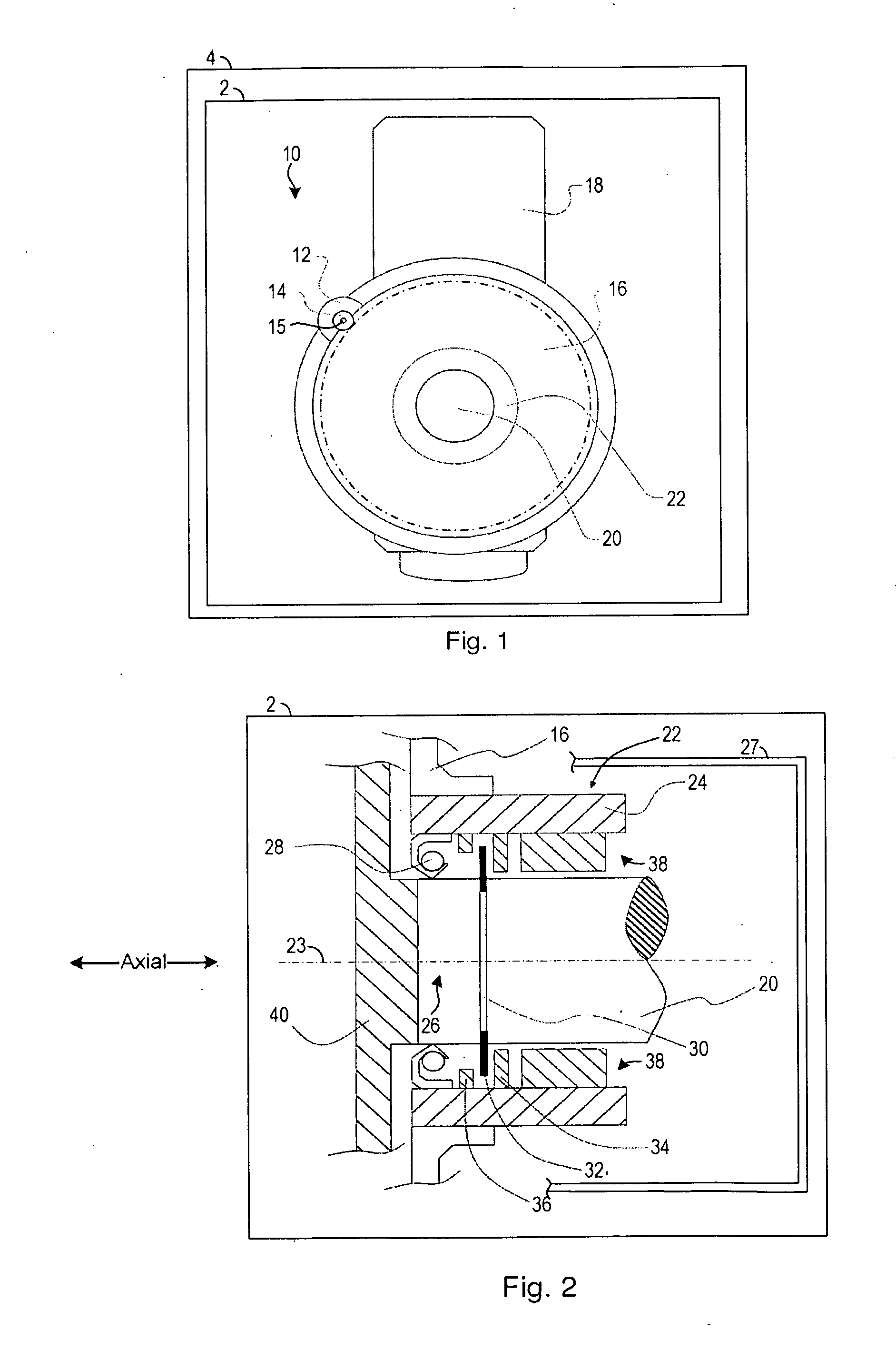
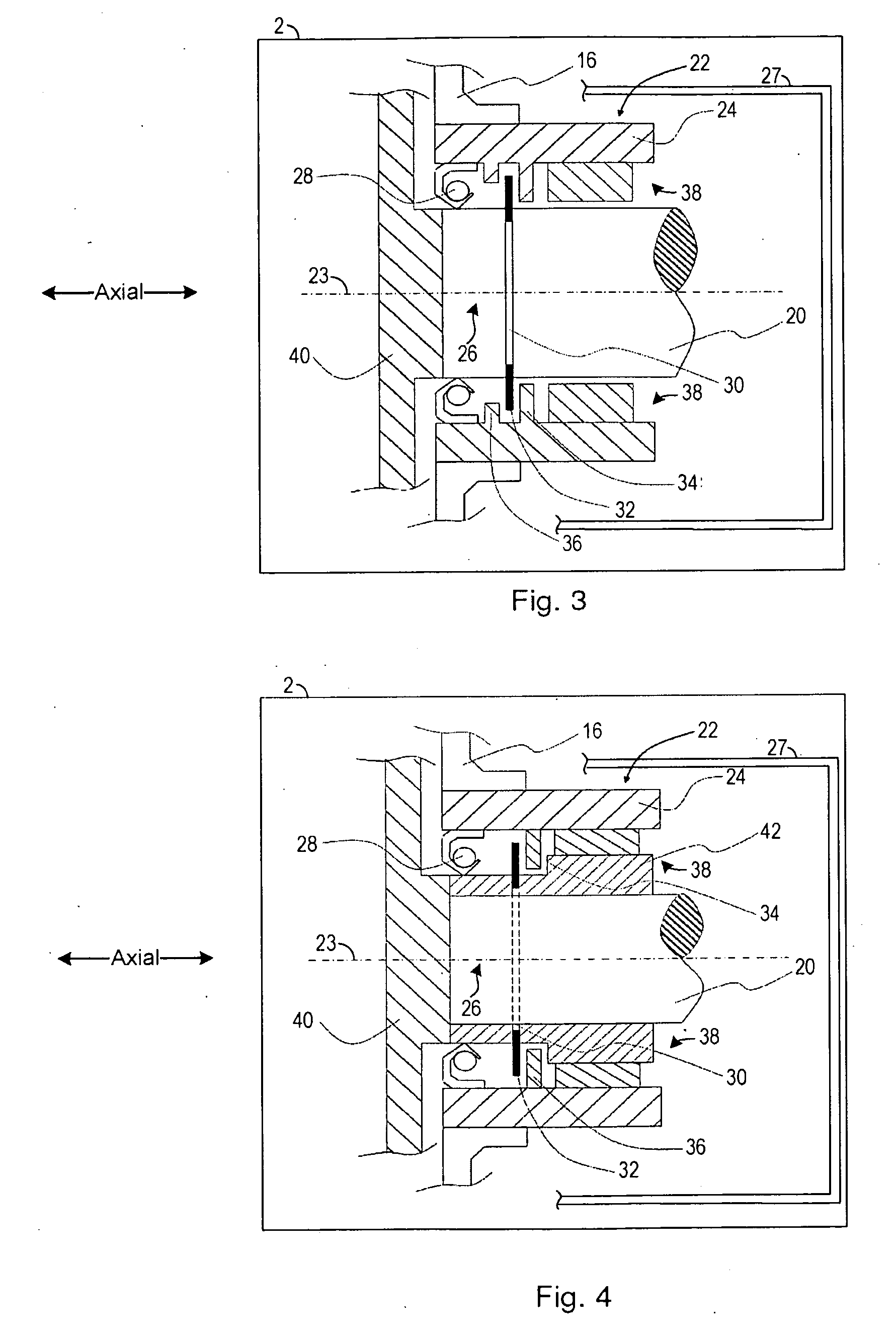
[0021]FIGS. 1-4 illustrate various examples of a starter arrangement 10 included in an internal combustion engine 2. The starter arrangement may be easily installed and removed, simplifying the manufacturing as well as the repair process of the internal combustion engine. In this way, the cost of the internal combustion engine and therefore the vehicle may be decreased.

[0022]In a first example of the present invention, as shown schematically in FIG. 1, a starter arrangement 10 for an internal combustion engine 2 is illustrated. The internal combustion engine may be included in an automotive vehicle 4. In some examples, the vehicle may be a hybrid vehicle configured to generate two sources of motive power to propel the vehicle. However, in other examples, the vehicle may be another suitable vehicle such as a truck, sedan, etc., utilizing an internal combustion engine as the exclusive source of motive power.

[0023]The starter arrangement 10 may include a starter motor 12, which may be ...


PUM


Abstract

A starter arrangement for an internal combustion engine the arrangement including a starter motor having a pinion gear coupled to an output shaft, the pinion gear being arranged in constant engagement with a corresponding crank gear of a crank wheel located between an engine block and a flywheel of the engine. The crank wheel is operatively coupled to a crankshaft of the engine via a one-way clutch unit loosely fitted to an end of the crankshaft, the crankshaft including a circumferential slot carrying a clip ring. The one-way clutch unit including a tube shaped hub loosely fitted to an end of the crankshaft, the axial movement of the one-way hub is fixed via a clip-ring in co-operation with a first axially delimiting member and a second axially delimiting member at least partially enclosed by the hub.

Description

CROSS REFERENCE TO RELATED APPLICATION[0001]This present application claims priority to European Application Number 07123346, filed Dec. 17, 2007, entitled “Starter Arrangement for an Internal Combustion Engine”, naming Peter Gast, Jonas Forssell, Lars Stenvall, and Petter Almhagen as inventors, the entire contents of which are incorporated herein by reference.TECHNICAL FIELD[0002]The present invention is related to a starter arrangement for an internal combustion engine. Furthermore, the present invention relates to a method for mounting a one-way clutch unit of a starter arrangement for an internal combustion engine.BACKGROUND OF THE INVENTION[0003]A so called start-stop or idle-stop arrangement is based on the concept of halting combustion in a vehicle's engine during vehicle standstill (e.g. when waiting for a traffic light to change from red to green). Such an arrangement may allow for substantial savings in fuel consumption. For mixed highway / rural and city driving savings of ...

Claims


Application Information

Patent Timeline
Patent Type & Authority Applications(United States)
IPC IPC(8): F02N11/00
CPCF02N11/0814Y10T74/134F02N2015/061F02N15/022
Inventor GAST, PETERFORSSELL, JONASSTENVALL, LARSALMHAGEN, PETTER
Owner VOLVO CAR CORP
Why Eureka
Try Eureka