Filling Machine Provided with a Cleaning in Place Device with Individual Collecting Elements

a technology of cleaning device and filling machine, which is applied in the direction of filling device cleaning, packaging goods type, liquid bottling, etc., can solve the problems of complicated cleaning, cumbersome and complicated means of moving and guiding, and the cleaning device has a substantial encumbrance in the lower portion of the machine, so as to achieve convenient carrying, easy mounting and dismounting, and effective compensation of positioning defaults

Inactive Publication Date: 2012-07-19
HEMA
View PDF1 Cites 5 Cited by
  • Summary
  • Abstract
  • Description
  • Claims
  • Application Information

AI Technical Summary

Benefits of technology

[0032]According to an embodiment, said upstream end of each collecting element is provided with sealing means through which said collecting element comes into contact with a filling spout, in order to guarantee the sealing between the filling spout and the collecting element in its service position, said sealing means comprising more preferably an annular inflatable membrane mounted at the upstream end of the collecting element and able to come in contact with the filling spout when it is in an inflated state and the collection tube is in its service position. The annular inflatable membranes make it possible to effectively compensate the positioning defaults of the individual collecting elements in relation to their respective filling spouts, i.e. the differences in height between the filling spouts and / or the differences in height between the collecting elements, and / or the alignment defaults of their vertical axes, and therefore to guarantee a sealed connection of all of the collecting elements of the machine with the filling spouts.
[0033]According to an embodiment, the annular inflatable membrane is able to come to bear against the lower edge of the filling spout, around the discharge opening, the membrane allowing to pass through its centre the cleaning agent exiting from the filling spout. According to another embodiment, said inflatable membrane is able to come laterally tighten the cylindrical wall of the filling spout. In this embodiment, the thrusting pressure is supported only by the filling spout. During cleaning operations, the membrane does not exert any vertical force on the filling spout, and it is therefore not necessary to reinforce the structure supporting the filling spouts, or that supporting the collecting elements. Moreover, the filling spouts can thus be easily carried directly by their supply ducts fixed rigidly in the lower portion of the distributing means, formed for example of a central tank, the dosing means being advantageously directly carried by the filling spout.
[0034]According to an embodiment, the inflatable membrane of a collecting element is mounted on the upper edge of the first tube of the collecting element by means of at least one flange fixed on said first tube by means of screws or threaded rods, and tightened from the upper edge of the flange, and / or tightened, where applicable by means of nuts, by the lower edge of said first tube, after insertion of screws or threaded rods in longitudinal bores of said first tube. Thus, the inflatable membranes can be easily mounted and dismounted.

Problems solved by technology

The vertical travel between the two positions is relatively substantial, and the cleaning device has a substantial encumbrance in the lower portion of the machine.
Cumbersome and complicated means for moving and guiding are required to carry out this vertical travel and guarantee a correct movement of all of the collecting elements in high position.
Their presence congests the plate of the machine, complicating its cleaning in case of accidental fouling.
However, their encumbrance may be incompatible with conventional systems for supporting containers.
Such a seal with an O-ring cannot be correctly provided on a machine provided with a large number of filling spouts, as in practice, the differences in height between the filling spouts cannot be compensated by the crushing of an O-ring.
These tubular tips cannot however be used in certain cases, in particular according to the type of filling spout and / or the type of system for support.

Method used


Image

  • Filling Machine Provided with a Cleaning in Place Device with Individual Collecting Elements
  • Filling Machine Provided with a Cleaning in Place Device with Individual Collecting Elements
  • Filling Machine Provided with a Cleaning in Place Device with Individual Collecting Elements

Examples


Embodiment Construction

)

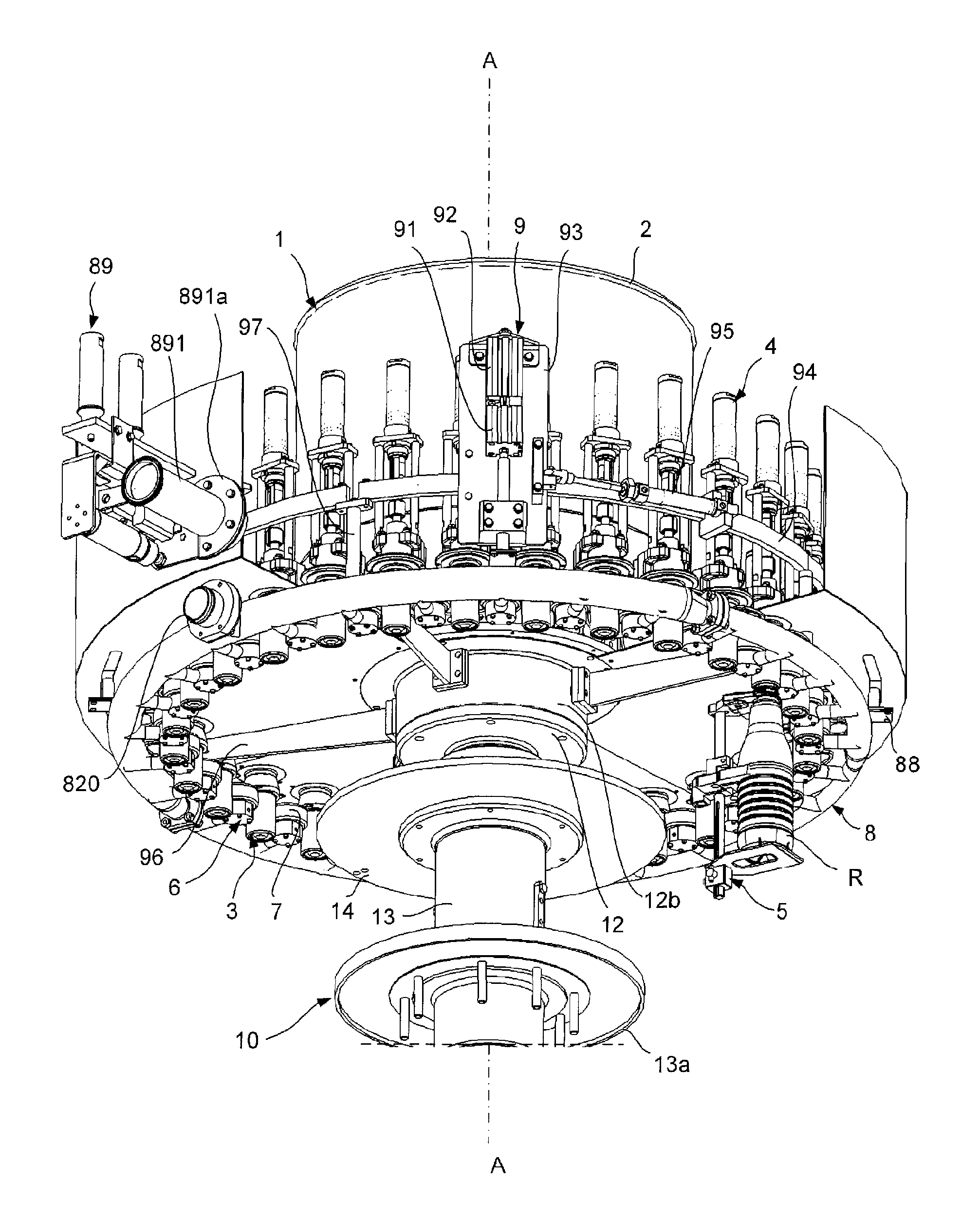
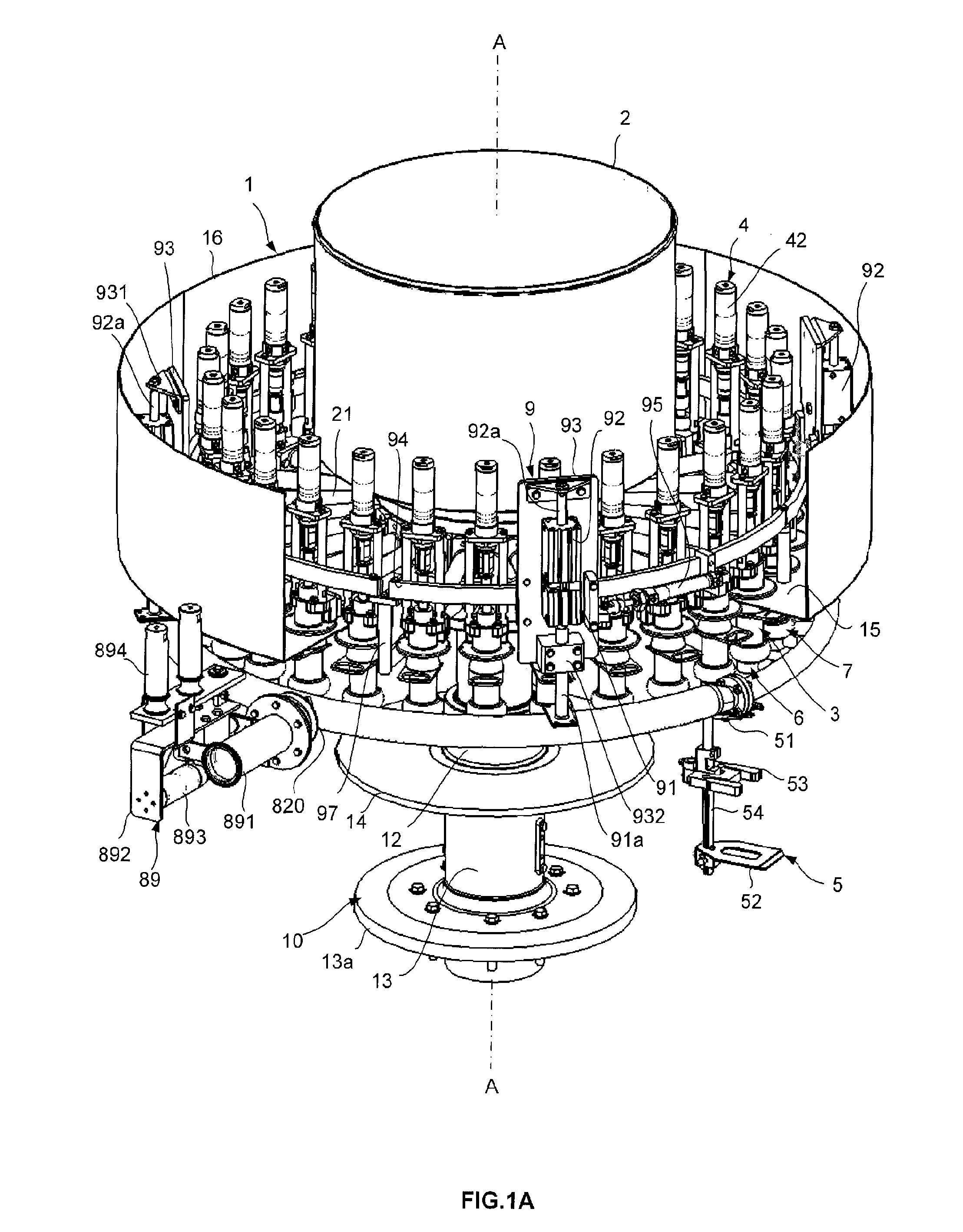
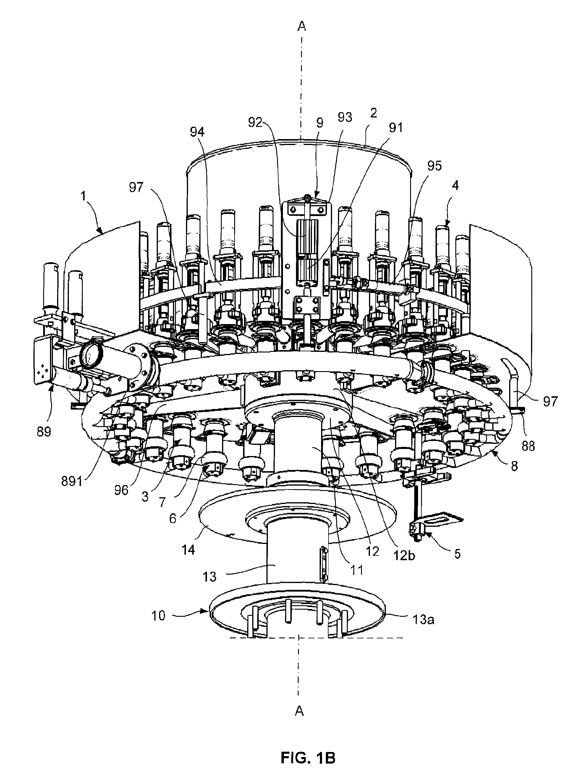
[0049]In the embodiment shown in the figures, in reference in particular to FIGS. 1A and 1B, the filling machine is of the rotating type, and comprises a carrousel 1 comprising a support structure 10, intended to be mounted rotating on a fixed frame (not shown) around an axis A of vertical rotation. The support structure carries means of distributing filling liquid formed here by a central cylindrical tank 2, and a plurality of filling stations arranged at regular angular intervals around the axis A. The support structure comprises an upper column or drum 11, provided at its upper end with a support crown 12 whereon is mounted a raising cylinder 12b supporting the tank, this upper column being mounted slidingly in a lower column 13 provided with a base 13a through which the support structure is mounted on the fixed frame. The two columns are integral in rotation, the upper column 11 being able to be moved vertically via suitable means between a high position and a low position, suc...


PUM

PropertyMeasurementUnit
flow velocityaaaaaaaaaa
displacementaaaaaaaaaa

Abstract

A machine for filling containers, including a plurality of filling spouts, and a cleaning device comprising a plurality of individual tubular collecting elements rigidly mounted on a collection tube, and a device for moving the collection tube between a retracted position and a service position in which the collecting elements are in contact, via the upstream ends thereof, with the filling spouts. The collection tube laterally supports the collecting elements, such that, in the retracted position, the collecting elements are arranged between the filling spouts. The moving device capable of moving the collection tube from the retracted position thereof to the service position thereof by at least one downward vertical translational movement, followed by a horizontal movement.

Description

BACKGROUND[0001]This invention relates to a filling machine provided with a cleaning in place device. The invention relates more particularly to a rotating machine provided with a plurality of filling spouts for the filling of hollow containers, such as bottles or pots, with any sort of products, liquids to viscous, in particular a food product, the cleaning device comprising individual collecting elements associated to said filling spouts.[0002]Such rotating filling machines conventionally include a rotating carrousel carrying a filling product tank and a plurality of filling stations, each filling station comprising a filling spout connected to the tank, a system for support making it possible to support a container under the filling spout, and dosing means in order to deliver a determined quantity of filling product into each container.[0003]Such machines must be cleaned on a regular basis using a cleaning agent, such as a cleaning solution (soda, acid, water or disinfectant) or ...

Claims


Application Information

Patent Timeline
Patent Type & Authority Applications(United States)
IPC IPC(8): B67C3/22
CPCB67C3/004
Inventor HUITOREL, MICKAELLE BERRE, ERIC
Owner HEMA
Why Eureka
Try Eureka