Cockpit instrument panel systems and methods with variable perspective flight display

a technology of variable perspective and instrument panel, which is applied in the field ofcockpit instrument panel systems and methods with variable perspective flight display, can solve the problems of inability to individually tailor the view to increase the comprehension of the pilot/user, the data presented within any one display is not necessarily well organized and structured, and the existing display does not permit views, etc., to achieve the effect of improving customization and efficient presentation

Inactive Publication Date: 2009-12-01
GARMIN INT
View PDF24 Cites 18 Cited by
  • Summary
  • Abstract
  • Description
  • Claims
  • Application Information

AI Technical Summary

Benefits of technology

[0013]The above mentioned problems related to customization and presentation of flight information data within cockpit displays, as well as other problems, are addressed by the present invention and will be understood by reading and studying the following specification. Systems and methods are provided for cockpit instrument panels and cockpit data presentation which provide better customization and more efficient presentation of flight information data within cockpit displays. The systems and methods of the present invention offer improved cockpit instrument panels which provide more integrated, user-intuitive, and efficient access to customizable, navigation related, flight information data.

Problems solved by technology

Accordingly, existing data views and / or data formats must be learned by the pilots / co-pilots, and the views cannot be individually tailored to increase the comprehension of the pilot / user, based on any preferences of the pilot / co-pilot.
Often, however, the select aircraft input controls are not integrated into a bezel surrounding the MFD, and sometimes such input controls are not even located in near proximity to the MFD.
Additionally, data presented within any one display is not necessarily well organized and structured to provide a meaningful integrated presentation to the pilot / co-pilot.
Moreover, existing displays do not permit views, within the display, to include useful overlays or graphical display insets of additional relevant data.
For example, a graphical view of an aircraft depicting the aircraft as it travels along a planned route toward a destination, generally does not permit the same graphical view to be overlaid with weather conditions occurring along the planned route, terrain conditions present along the planned route, and / or traffic conditions occurring along the planned route relative to other aircraft flying in close proximity to the planned route.
And, even if some overlaid view or graphical display inset is permitted, existing views do not allow the perspective of that view to be altered.
To further emphasize the problems associated with providing customization with existing MFDs, consider that conventional MFDs are not easily expanded to include additional functionality as a pilot / user desires.
As a result, MFDs are not flexible and any modifications that require additional functionality, to support expanded display (e.g., view) integration features, requires expensive design modifications to the control inputs, the control devices, and the software driving the presentation of data on the MFDs.
As is apparent to one skilled in the art, existing cockpit control systems and cockpit instrument displays do not provide seamless integration with respect to communication controls, navigational controls, and equipment controls or instruments, or for the instrument displays which present data views associated with these controls and instruments.
Consequently, the pilot / user is often forced to view scattered, multiple instrument displays to obtain all the relevant flight information data associated with the controls or instruments.

Method used


Image

  • Cockpit instrument panel systems and methods with variable perspective flight display
  • Cockpit instrument panel systems and methods with variable perspective flight display
  • Cockpit instrument panel systems and methods with variable perspective flight display

Examples


Embodiment Construction

[0020]In the following detailed description of the invention, reference is made to the accompanying drawings which form a part hereof, and in which is shown, by way of illustration, specific embodiments in which the invention may be practiced. The embodiments are intended to describe aspects of the invention in sufficient detail to enable those skilled in the art to practice the invention. Other embodiments may be utilized and changes may be made without departing from the scope of the present invention. The following detailed description is, therefore, not to be taken in a limiting sense, and the scope of the present invention is defined only by the appended claims, along with the full scope of equivalents to which such claims are entitled.

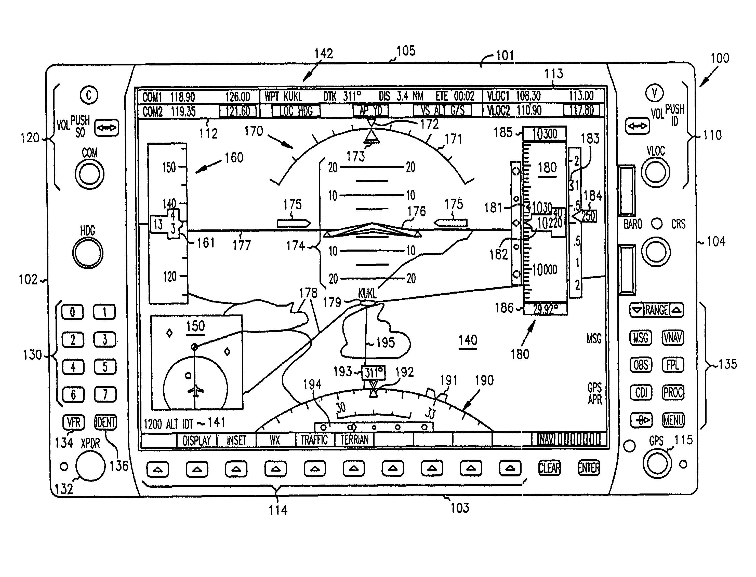
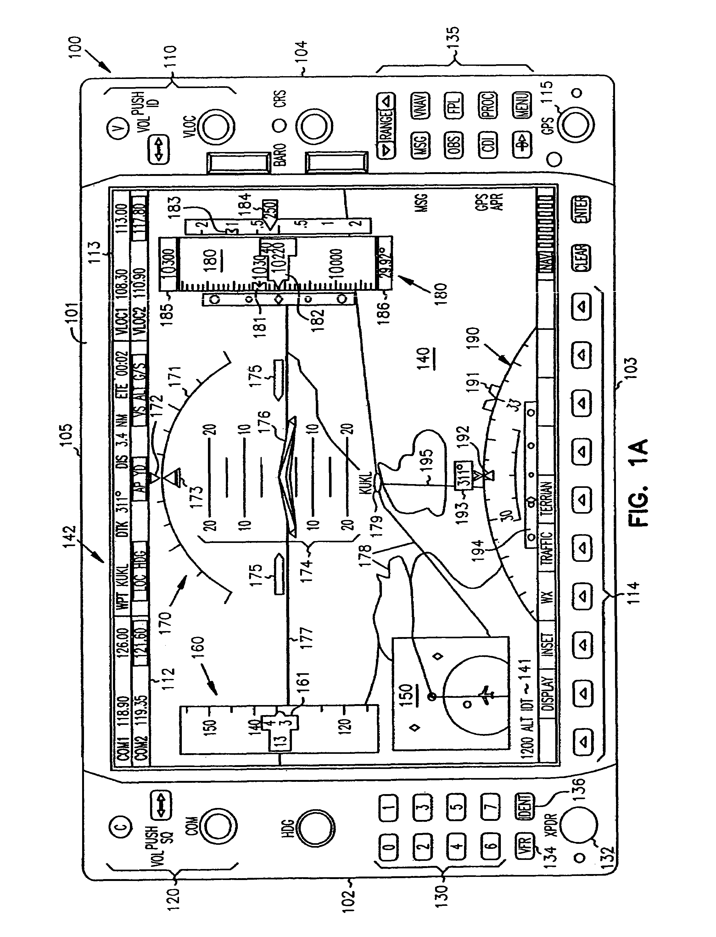
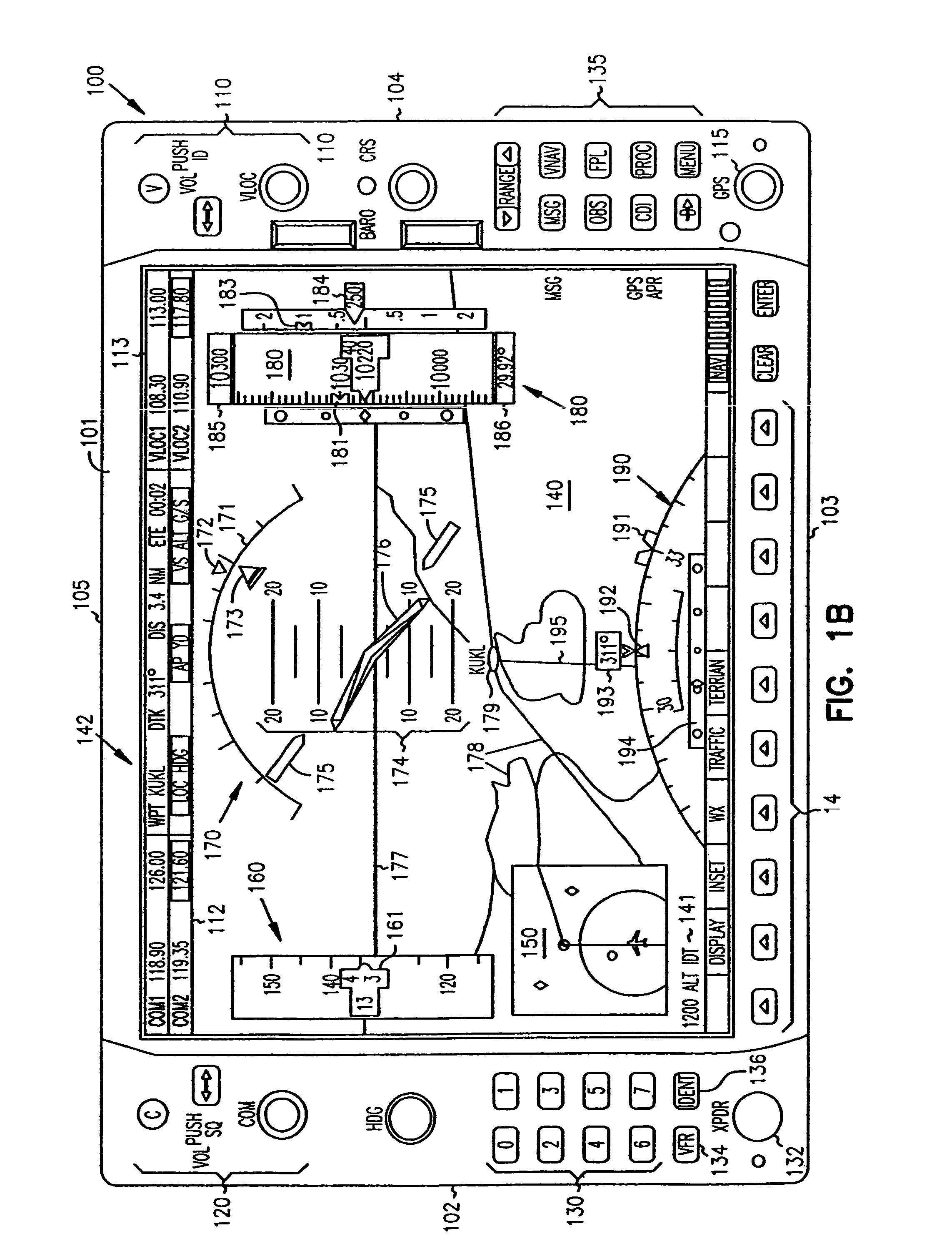
[0021]In the present invention, improved multifunction displays (MFDs) are provided. As used herein, a MFD is used broadly to include graphical user interface based (GUI-based) displays with integrated presentation data presented thereon using a ...


PUM


Abstract

Systems and methods are provided for integrated control, access, and customizable presentation of navigation related, flight information data on a multifunction display (MFD) within a cockpit. The MFD includes a bezel having controls located thereon which are adapted for controlling display formats, communication devices, navigational devices, and equipment sensors. A display is located adjacent to the bezel. The display is adapted to include at least one display region having navigation related data. At least one of the controls is operable to variably select a display format for the at least one display region.

Description

CROSS REFERENCE TO RELATED APPLICATIONS[0001]The present application is a continuation application of U.S. patent application Ser. No. 10 / 086,573, filed Feb. 28, 2002 now U.S. Pat. No. 6,867,711.[0002]This application is related to the following co-pending, commonly assigned U.S. patent applications: “Cockpit Instrument Systems and Methods of Presenting Cockpit Instrument Data”, Ser. No. 10 / 086,951, now U.S. Pat. No. 6,696,980; “Cockpit Control Systems and Methods of Controlling Data on Multiple Cockpit Instrument Panels”, Ser. No. 10 / 086,929; “Cockpit Display Systems and Methods of Presenting Data on Cockpit Displays”, Ser. No. 10 / 986,598; “Cockpit Control Systems and Methods with Redundant Flight Data Display”, U.S. Ser. No. 10 / 086,783; and “Customizable Cockpit Display Systems and Methods of Customizing the Presentation of Cockpit Data”, Ser. No. 10 / 086,996, each of which is by the same inventors and of which the disclosure is herein incorporated by reference in its entirety.COPY...

Claims


Application Information

Patent Timeline
Patent Type & Authority Patents(United States)
IPC IPC(8): G01C21/00G01C23/00
CPCG01C23/00G01D2207/10
Inventor LANGNER, DALE R.STRAUB, PHILIP I.
Owner GARMIN INT
Why Eureka
Try Eureka