
Method for making leg model and orthopedic brace

a leg model and model technology, applied in the field of orthopaedic braces, can solve the problems of long process, inconvenient patient and doctor, inability to raise the patient's foot to avoid obstacles, etc., to achieve the effect of improving the adherence of casting materials, facilitating better customization of model parts, and facilitating the adhesion of fairing materials

Inactive Publication Date: 2006-02-16
ENGELMAN IAN
View PDF3 Cites 4 Cited by
  • Summary
  • Abstract
  • Description
  • Claims
  • Application Information

AI Technical Summary

Benefits of technology

[0007] An object of the invention is to eliminate the necessity for the laborious process of making a cast on the patient lower leg and / or foot and making a positive model for the construction of an AFO. (For simplicity, the model will related to as a leg model, however it is to be understood that the reference to a leg should be construed as relating to the whole leg, the foot portion, or a portion of a leg or foot as will be the common meaning of such term in the context in which it is used).
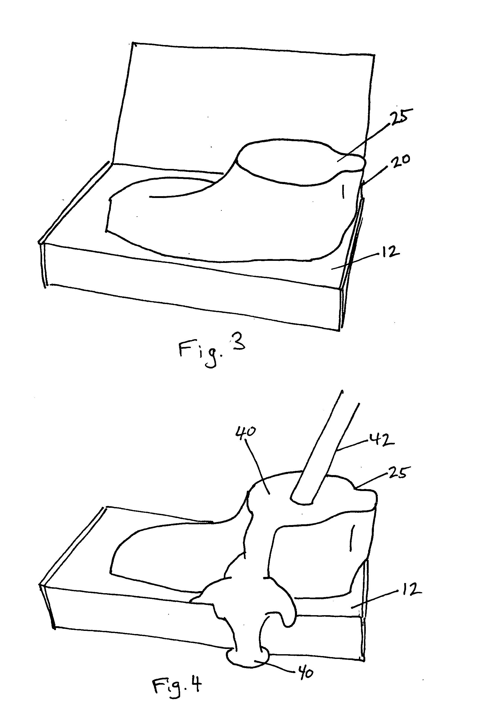
[0012] Optionally the upper portion further has at least one cavity, to allow casting material to flow into said cavity to provide improved adherence of the casting material to the upper portion, or to form the coupling. Further optionally, the upper portion may have a conduit therein, for pouring casting material to said impression. The upper portion positive preferably comprises at least one textured surface to ease adhering of fairing materials thereto.
[0013] Optionally, the invention further comprises the steps of photographing the patient's foot, and extrapolating measurements of the foot to facilitate better customization of model portions like the calf or ankle.

Problems solved by technology

For example, as a result of a stroke or some other medical conditions, the patient's foot cannot be raised to avoid obstacles.
This may be dangerous, since the patient can trip.
This process is lengthy, laborious, and is inconvenient to the patient and to the doctor.

Method used


Image

  • Method for making leg model and orthopedic brace
  • Method for making leg model and orthopedic brace
  • Method for making leg model and orthopedic brace

Examples


Embodiment Construction

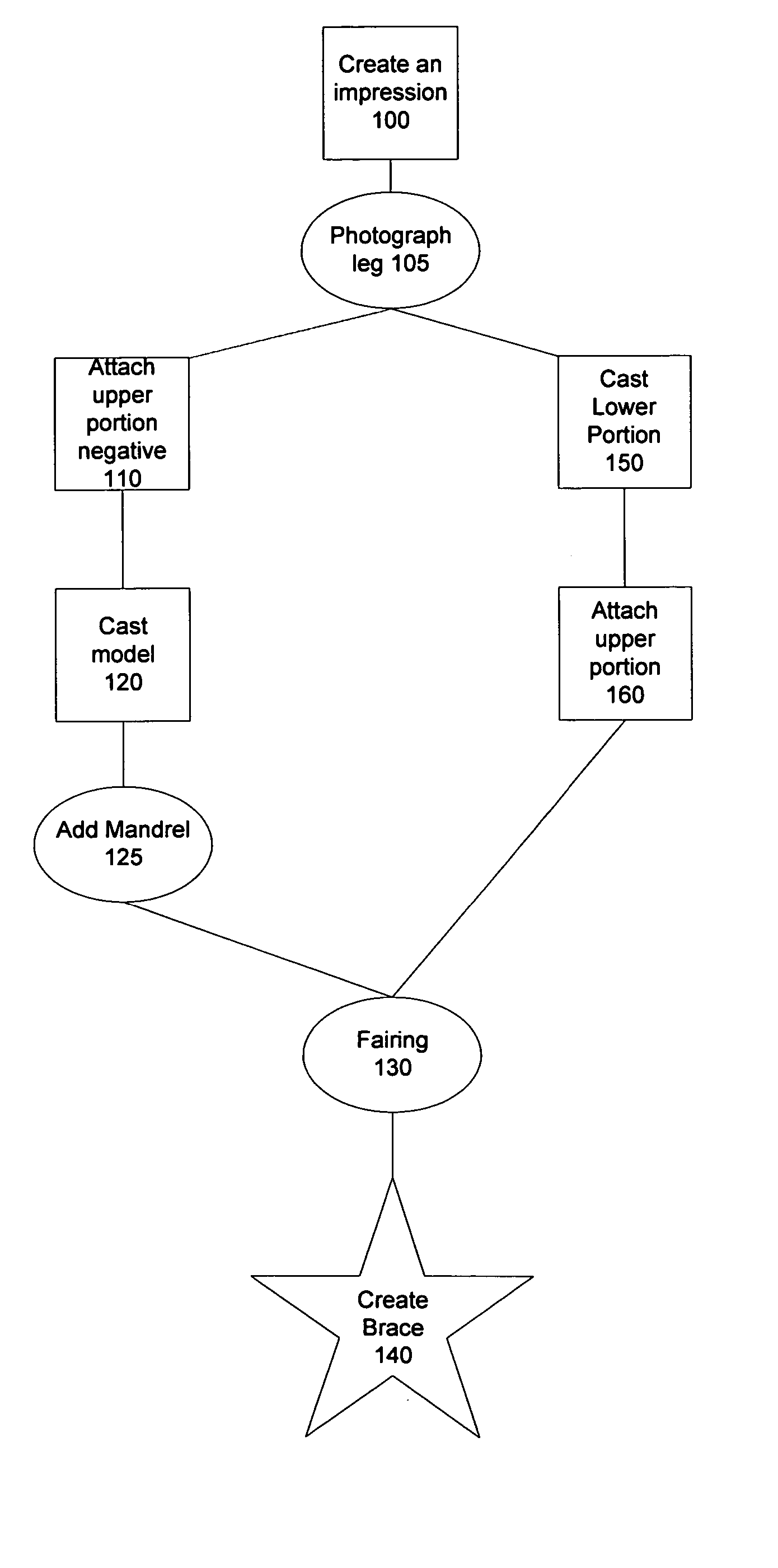
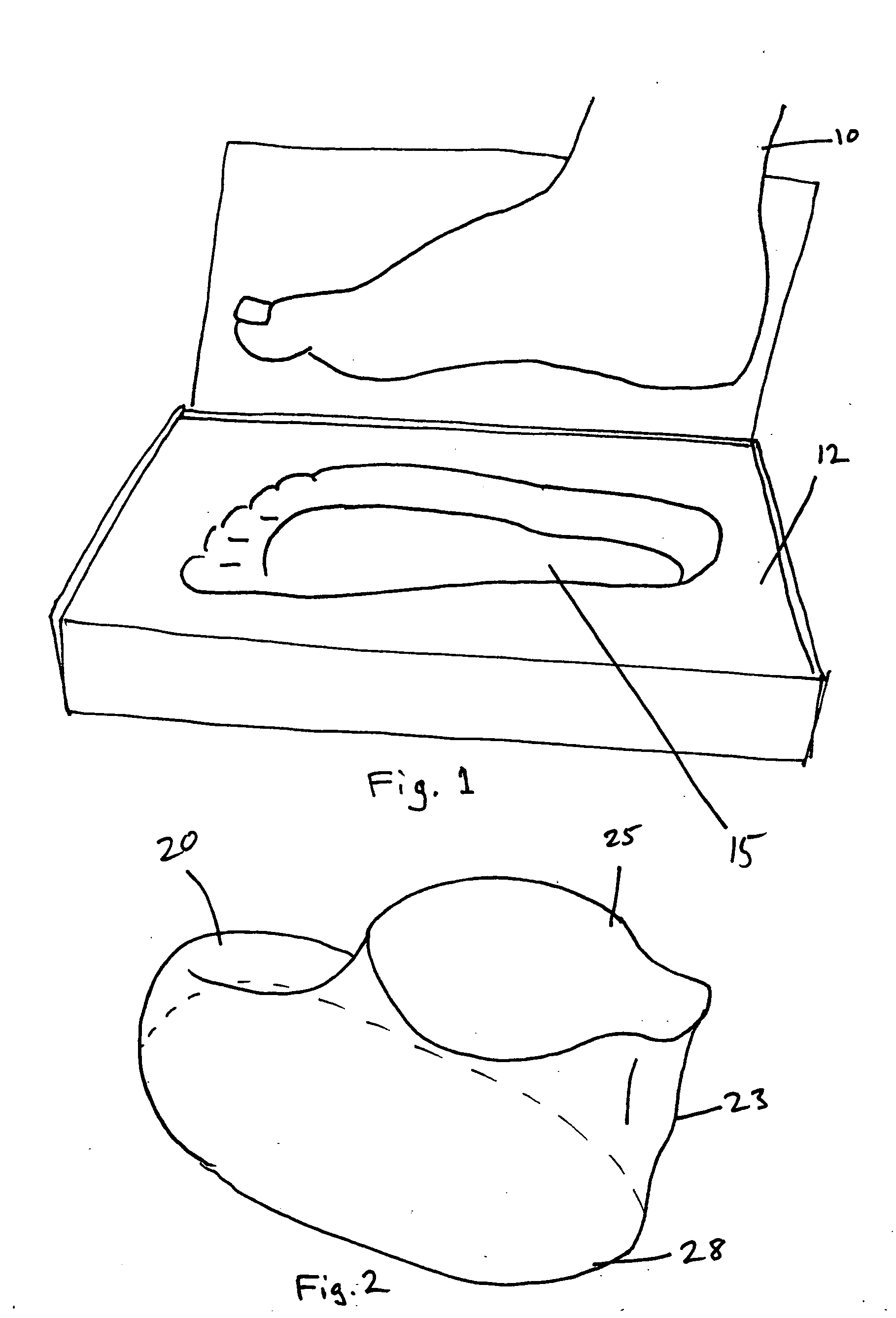
[0029]FIG. 1 presents the first step (100 in FIG. 11) in the preferred embodiment of the invention. The patient's foot 10 is pressed into an impression block 12 to cause an impression 15. The preferred method utilizes a crush box where the deformable material of the impression block comprises easily deformable foam block, that is being crushed under pressure, preferably by having the patient step onto the impression block, to approximate the shape of the plantar contour of the patient's foot. The impression block may be of uniform or variable thickness and may be made of uniform material or from materials having varying degrees of hardness to provide more accurate measurement, or for other desired physical characteristics if desired. Optionally, the patient's foot is also photographed 105 to provide a vehicle from which measurements can be calculated, and / or measurements of areas such as the width and circumference of the leg can be obtained.

[0030] Several options exist for creatin...


PUM

PropertyMeasurementUnit
Flow rateaaaaaaaaaa
Areaaaaaaaaaaa

Abstract

A method for making a model or a partial model of a leg is based on taking measurements of the plantar area of the foot utilizing a crushable impression block such as a crush box to create a three dimensional impression, and using the impression to cast a leg model from which a brace may be made.

Description

FIELD OF INVENTION [0001] The invention relates in general to orthopedic braces, and more particularly to a method of making a leg model and a brace (orthosis) utilizing the model. BACKGROUND [0002] Braces are used extensively in the orthopedic arts to provide added support to limbs requiring such support as a result of a variety of medical conditions. These specifications will use one such brace as a generalized example for a brace commonly known as an Ankle Foot Orthosis (hereinafter an AFO). It will be clear to those skilled in the art that in light of these specifications and the accompanying drawings, the application of the invention may be extended to leg braces other than an AFO, and the specifications and claims should be so interpreted. [0003] An AFO is a medical device that assists patients who have lost at least partial control over the angle in which they can maintain their foot respective to their leg. For example, as a result of a stroke or some other medical condition...

Claims


Application Information

Patent Timeline
IPC IPC(8): B29C33/40
CPCB29C33/3857A61F5/14
Inventor ENGELMAN, IAN
Owner ENGELMAN IAN
Learn More