Optimized machining process for cutting tubulars downhole

a tubular device and machining process technology, applied in the field of tubular member separation, can solve the problems of unusable tubular device parts and replacement, and achieve the effect of improving the quality of tubular parts and reducing the cost of replacemen

Inactive Publication Date: 2009-12-08
BAKER HUGHES HLDG LLC
View PDF37 Cites 14 Cited by
  • Summary
  • Abstract
  • Description
  • Claims
  • Application Information

AI Technical Summary

Problems solved by technology

From time to time, portions of such tubular devices may become unusable and require replacement.

Method used


Image

  • Optimized machining process for cutting tubulars downhole
  • Optimized machining process for cutting tubulars downhole
  • Optimized machining process for cutting tubulars downhole

Examples


Embodiment Construction

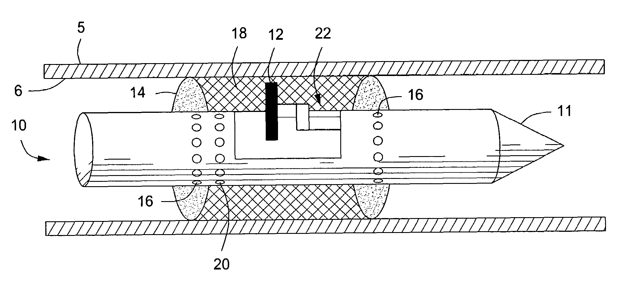
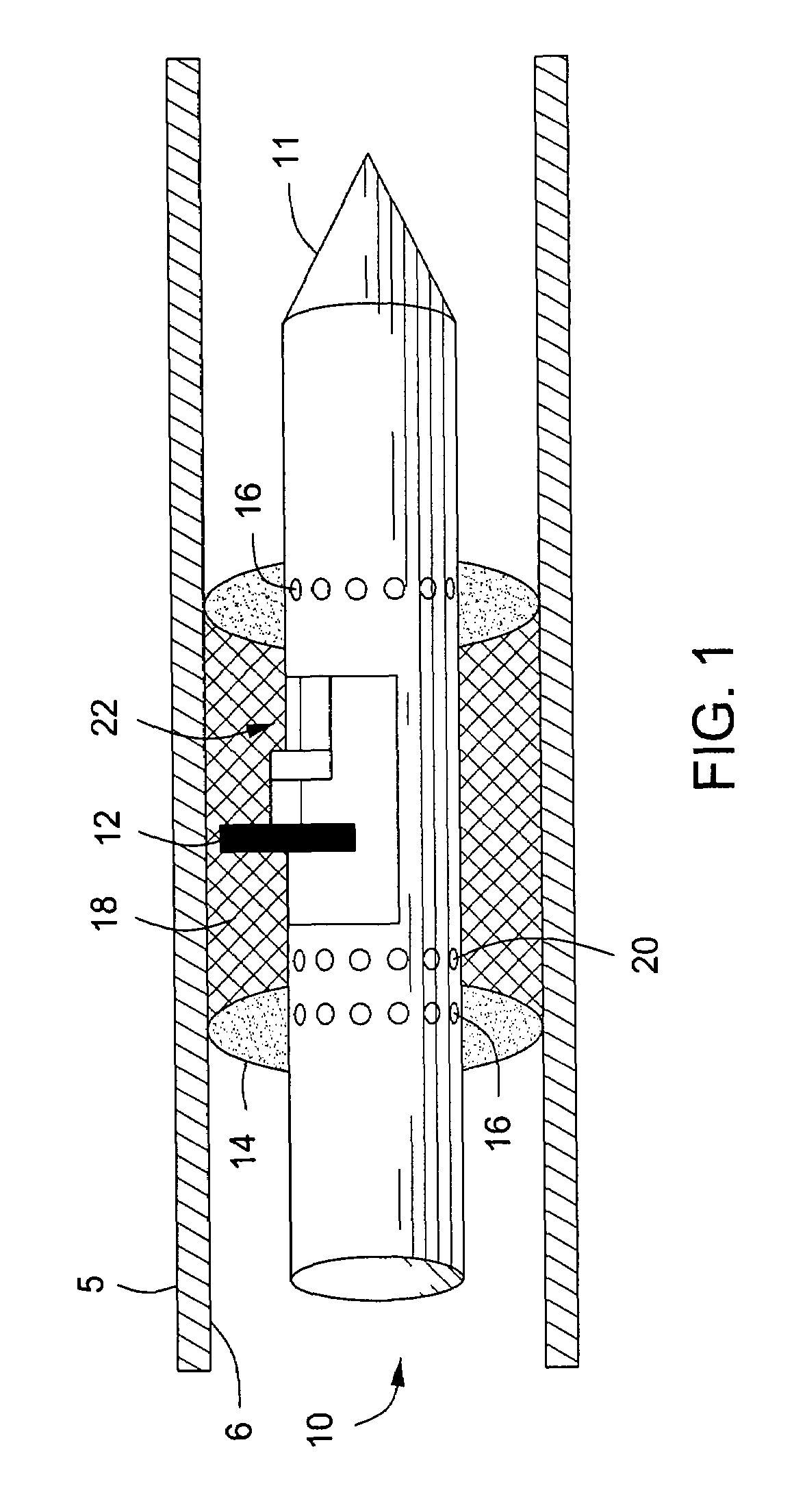
[0013]Described herein is a method and apparatus for cutting and severing a tubular. While the apparatus and method described herein may be used to cut any type and length of tubular, one example of use involves severing tubing disposed within a wellbore, drill pipe, wellbore tubular devices, as well as wellbore casing. One embodiment of a cutting tool 10 as described herein is shown in side partial cut away view in FIG. 1. In this embodiment, the cutting tool 10 comprises a body 11 disposed within a tubular 5. As noted, the tubular 5 may be disposed within a hydrocarbon producing wellbore, thus in the cutting tool 10 may be vertically disposed within the wellbore tubular. Means for conveying the cutting tool 10 in and out of the wellbore include wireline, coiled tubing, slick line, among others. Other means may be used for disposing the cutting tool 10 within a particular tubular. Examples of these include drill pipe, line pigs, and tractor devices for locating the cutting tool 10 ...


PUM

PropertyMeasurementUnit
timeaaaaaaaaaa
lengthaaaaaaaaaa
circumferenceaaaaaaaaaa

Abstract

The tubular cutter disclosed herein is useful for severing downhole tubulars and comprises a drive system, a pivoting system, a cutting head, and a cutting member. Cutting is accomplished by rotatingly actuating the cutting head with an associated motor, and then radially extending the cutting blade away from the cutting head. In one embodiment, the cutting head includes a cutting member that pivotally extends from the cutting head upon rotation of the cutting head.

Description

BACKGROUND OF THE INVENTION[0001]1. Field of the Invention[0002]The disclosure herein relates generally to the field of severing a tubular member. More specifically, the present disclosure relates to an apparatus for cutting downhole tubulars. Yet more specifically, described herein is a method and apparatus for optimizing cutting tubulars wherein lubrication is maintained between the cutting member and the tubular.[0003]2. Description of Related Art[0004]Tubular members, such as production tubing, coiled tubing, drill pipe, casing for wellbores, pipelines, structural supports, fluids handling apparatus, and other items having a hollow space can be severed from the inside by inserting a cutting device within the hollow space. As is well known, hydrocarbon producing wellbores are lined with tubular members, such as casing, that are cemented into place within the wellbore. Additional members such as packers and other similarly shaped well completion devices are also used in a wellbore...

Claims


Application Information

Patent Timeline
Patent Type & Authority Patents(United States)
IPC IPC(8): E21B29/00
CPCE21B29/005E21B33/1208B23D45/128B23D21/14B23B27/08B23B27/10B23B29/03457B23B2215/72
Inventor FUHST, KARSTENKRUEGER, SVEN
Owner BAKER HUGHES HLDG LLC
Why Eureka
Try Eureka