
Low profile vehicle turntable

a low-profile, turntable technology, applied in vehicle maintenance, vehicle-manoeuvring devices, transportation and packaging, etc., can solve the problem of extensive installation work in the area

Active Publication Date: 2009-12-15
SCHWENKER WILLIAM V
View PDF24 Cites 23 Cited by
  • Summary
  • Abstract
  • Description
  • Claims
  • Application Information

AI Technical Summary

Benefits of technology

[0023]This improved turntable device is designed for parking, displaying, rotating and maneuvering vehicles or other large or heavy items. Is has the significant advantage over prior art in that the turntable can be installed and operated on asphalt, cement, carpet, marble or any reasonably smooth surface. It can be installed permanently or it can be portable. Another significant advantage is that the drive motors are integrated and hidden inside the ramps around the circumference of the turntable, therefore nothing protrudes above the surface pan of the turntable. Drive motors do not have to be high powered. One embodiment operates with only ⅓ horsepower motors. Also the turntable can be entered or exited from any point on the outer circumference. Another advantage is that there is nothing protruding above the surface pan which can hit a low automobile air dam or chassis component on a vehicle or other item with low ground clearance. These advantages exist in the present invention because the drive mechanism is completely inside the ramps themselves. These ramps encircle the wedge shaped sections completely.
[0025]Another unique feature of the invention is the spider pressure notch. This is an indentation which runs the longitudinal length of the bottom of each individual ramp section to allow the outer circular rim band underneath each half of each ramp section to assist more effectively in distributing the shock load of a car's tire when it first hits the ramp section as the vehicles drive over them. This notch is continuous and sits on top of the outer circular band. The anchor bolts of a permanent installation of the invention would eventually loosen if the spider pressure notch was not present to distribute the shock load as the vehicle tires first hit the ramp sections.
[0026]A “motorcycle type suspension system” of the type often used on rear wheels of motorcycles has been adapted for use on the drive motors for this turntable which further compensates for uneven points on the surface the turntable rests upon. This suspension system keeps the pressure on the drive rollers that move the turntable constant and sufficient to efficiently rotate it as required. There is no need for cement work or drilling holes when installing this device. Except on low friction surfaces, the turntable spider assembly is held in place by the weight of the turntable itself, and all of the components of the turntable attach to the concentric and perpendicular bands making up the spider system. This avoids problems encountered by other types of turntables which require that bolts or anchors be placed into the mounting surface during installation. Bolts or anchors placed into the mounting surface are subject to hitting rebar or stones, a complication avoided by the current invention.
[0027]In addition, installation using the spider system allows installation upon degraded surfaces such as cracked cement, granulated asphalt, brick, carpet or marble where drilling holes would not be effective or desired. The spider also allows a broader mounting surface for the ramp units. On low friction surfaces anchoring means such as bolts or screws can be inserted through the spider bands and into the surface it rests on.

Problems solved by technology

The installation required extensive work in the area to be installed.

Method used


Image

  • Low profile vehicle turntable
  • Low profile vehicle turntable
  • Low profile vehicle turntable

Examples


Embodiment Construction

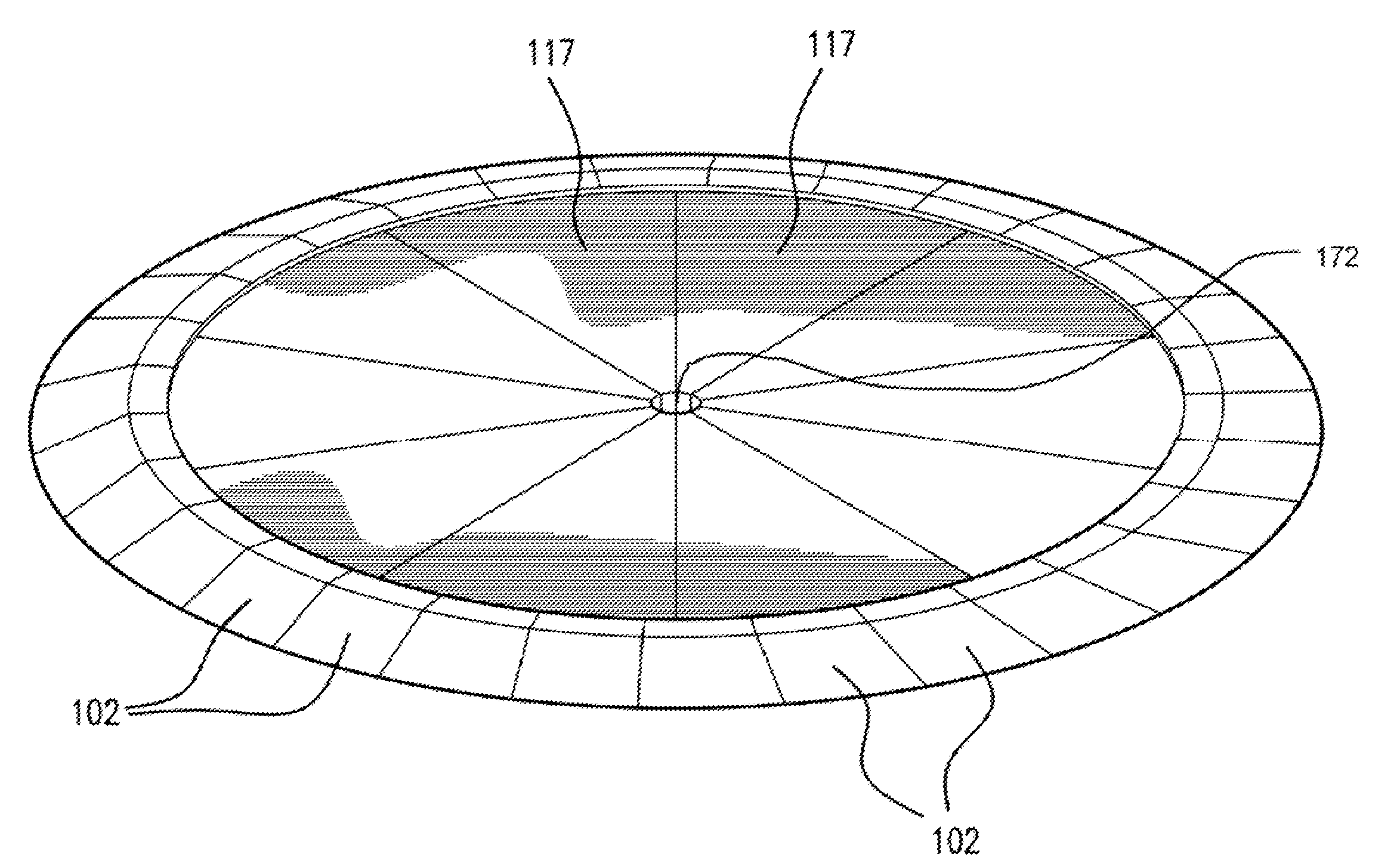
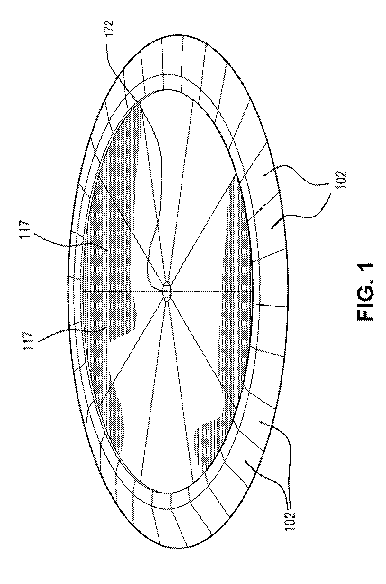
[0053]FIG. 1 shows a perspective view from above of a completely assembled turntable. The individual ramp sections around the exterior of the turntable (102) are shown around the circumference with the pan formed of a plurality of individual foam filled wedge shaped sections (117) joined on each side to a neighbor by a tongue and groove connector system more completely shown in FIG. 11. These wedge shaped sections meet at the narrow ends at a central point covered by a center cover band (172) The preferred embodiment is 10 sections but a lesser or greater number could be used if desired. Each wedge shaped section is comprised of a wedge shaped top and bottom skin placed over a wedge shaped section of structural foam.

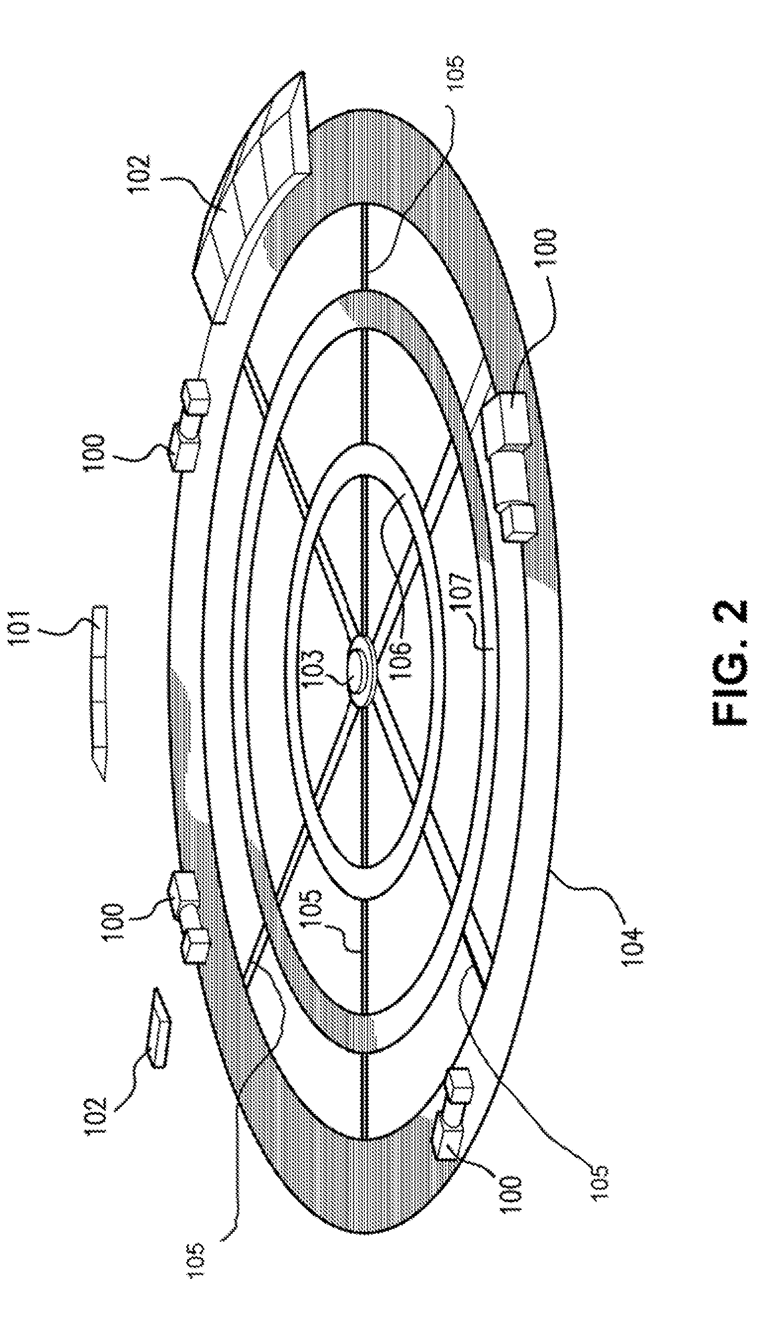
[0054]FIG. 2 shows a perspective view from above of the plurality of concentric circular bands anchored beneath the rotating portion of the turntable (104, 106, and 107). These concentric bands are each connected to one or more neighboring concentric circular bands by pe...


PUM


Abstract

A low profile turntable device constructed of wedge shaped sections with structural foam in between, support rollers on the bottom skin, a plurality of reversible drive motors inside a plurality of outer ramps around the exterior, and a concentric circular and perpendicular lateral band system for mounting the turntable on a surface.

Description

CROSS-REFERENCE TO RELATED APPLICATIONS[0001]This application is entitled to the benefit of the U.S. provisional patent application No. 60 / 810,577 filed Jun. 2, 2006 with the United States Patent Office. It is also related to U.S. Pat. No. 6,817,300 B2 in that it is by the same inventor.STATEMENT REGARDING FEDERALLY SPONSORED RESEARCH FOR DEVELOPMENT[0002]No Federal Funds were used in the development of this Invention.THE NAMES OF THE PARTIES TO A JOINT RESEARCH AGREEMENT[0003]Not Applicable.INCORPORATION-BY-REFERENCE OF MATERIAL SUBMITTED ON A COMPACT DISC[0004]Not Applicable.BACKGROUND OF THE INVENTION[0005]1. Field of the Invention[0006]There is a need for an inexpensive, easily installed low profile turntable which does not require extensive installation work. This invention has the advantage of only needing a flat surface area sufficient to accommodate the turntable itself, and a sufficiently flat surface to which the invention can be affixed. Vehicles or heavy loads can enter ...

Claims


Application Information

Patent Timeline
Patent Type & Authority Patents(United States)
IPC IPC(8): B60S13/02
CPCB60S13/02
Inventor SCHWENKER, WILLIAM V.
Owner SCHWENKER WILLIAM V
Learn More