Common link dual arm tensioning device

a tensioning device and common link technology, applied in the direction of belts/chains/gearrings, mechanical devices, belts/chains/gears, etc., can solve the problems of unreliable tensioning, one tensioning arm is incapable of absorbing the chain length increase, and the chain length increase is over time. , to achieve the effect of increasing tension and increasing tension

Inactive Publication Date: 2009-12-15
BORGWARNER INC
View PDF15 Cites 6 Cited by
  • Summary
  • Abstract
  • Description
  • Claims
  • Application Information

AI Technical Summary

Problems solved by technology

As a chain wears, the distance between the links increases, leading to an overall increase in the length of the chain over time.
In an engine timing system having overhead cams, an auxiliary drive on the slack strand is often positioned such that one tensioning arm is incapable of absorbing the chain length increase due to wear, both above and below the auxiliary drive.
Using two separate tensioning systems is an obvious first consideration, but it is often desirable to tension two strands either proportionally or equally, and the probability of separate systems tensioning equally is unreliable, leaving the preferred approach to simultaneous reaction being connecting the two arms with pins and links.

Method used


Image

  • Common link dual arm tensioning device
  • Common link dual arm tensioning device
  • Common link dual arm tensioning device

Examples


Embodiment Construction

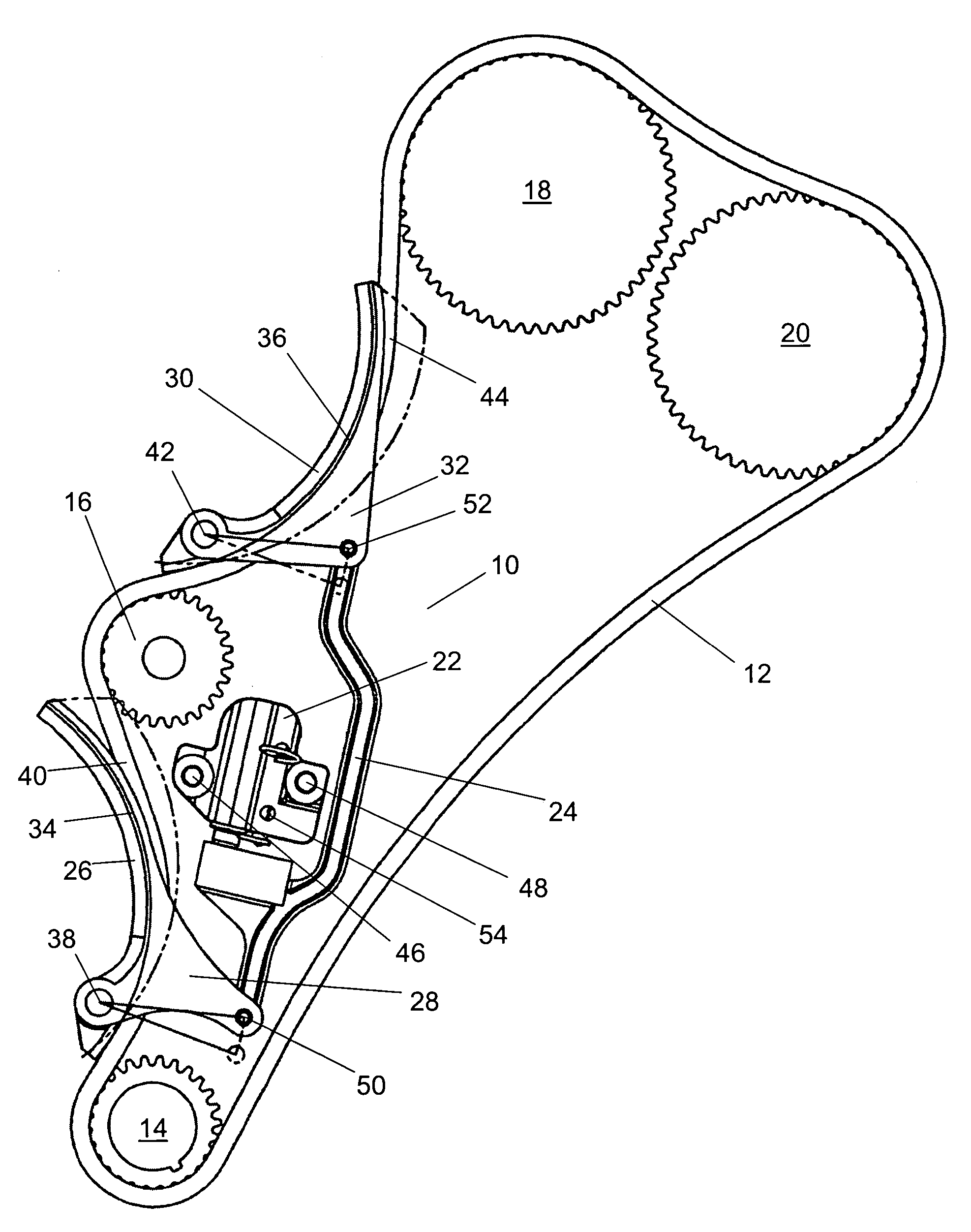
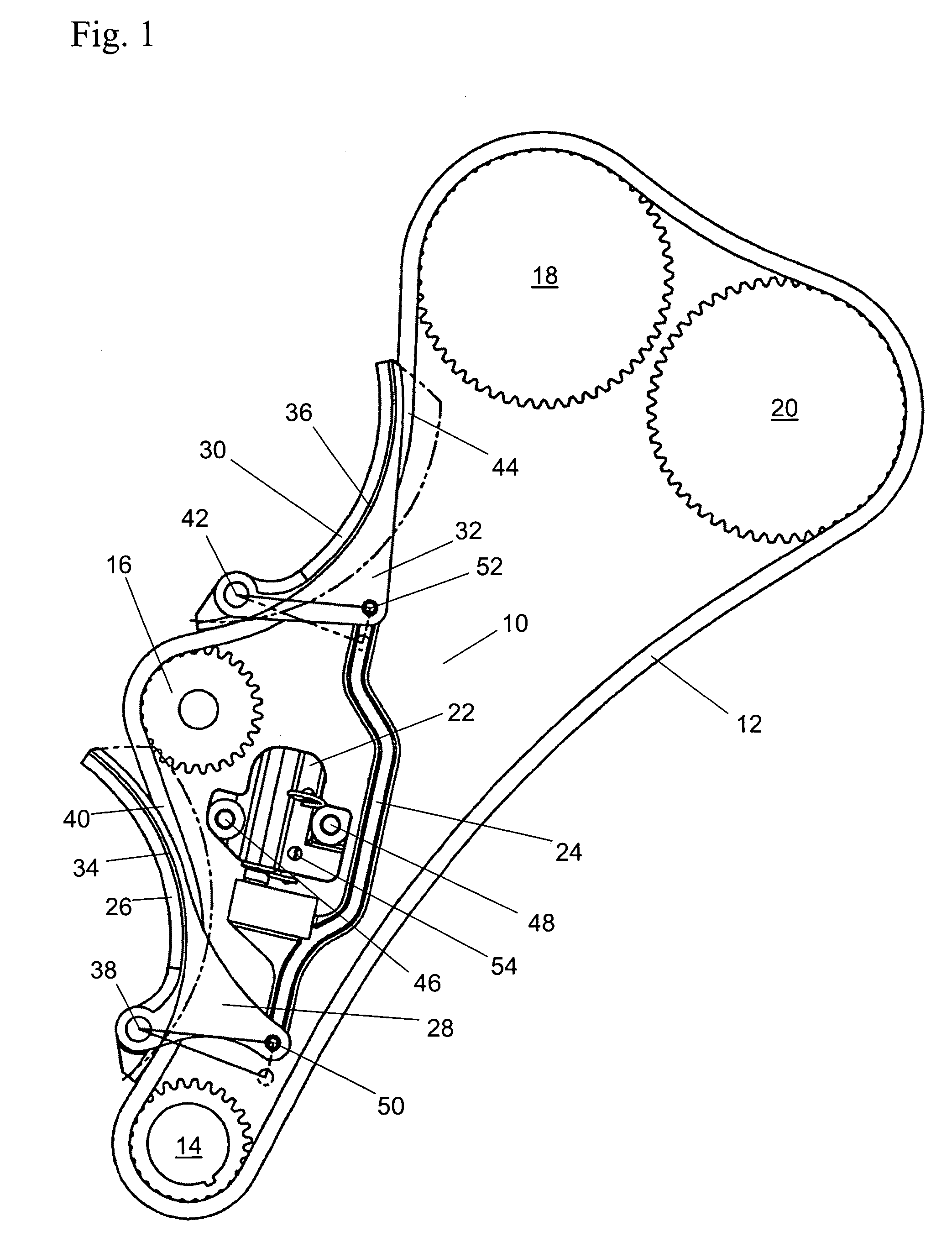
[0024]The present invention simultaneously tensions two strands of a multi-strand chain system. The invention is preferably used to tension a pair of slack strands flanking a sprocket. The usefulness of the present invention is illustrated in an engine timing system having overhead cams and an auxiliary drive on the slack strand positioned such that one tensioning arm is incapable of absorbing the chain length increase due to wear both above and below the auxiliary drive. The present invention is also applicable to tensioning belts.

[0025]When the two arms are linked, their relationship is fixed. Should the chain at one arm wish to act independently, it is resisted by the force available for the control of both arms. Thus, the chain tensioner provides greater chain control and better damping possibilities than single tensioning devices each having half the available force of both arms.

[0026]A chain tensioner of the present invention is adaptable to various lengths and various positio...


PUM


Abstract

A chain tensioning device links multiple tensioning arms to a common link, causing the tensioning arms to rotate into and displace chain strands with a single applied force and motion. The two tensioning arms rotate and tension proportionally, and when the pivot pin distances are equal, the two tensioning arms rotate and tension equally. The chain tensioner is preferably used to tension two slack chains flanking an auxiliary drive shaft. The chain tensioner is biased against the chain by a hydraulic tensioning assembly in one embodiment and by a spring tensioning assembly in another embodiment.

Description

BACKGROUND OF THE INVENTION[0001]1. Field of the Invention[0002]The invention pertains to the field of chain tensioners. More particularly, the invention pertains to a dual arm tensioner for tensioning strands flanking an auxiliary drive sprocket.[0003]2. Description of Related Art[0004]As a chain wears, the distance between the links increases, leading to an overall increase in the length of the chain over time. In many situations it is desirable to tension more than one strand of a multi-strand chain simultaneously. In an engine timing system having overhead cams, an auxiliary drive on the slack strand is often positioned such that one tensioning arm is incapable of absorbing the chain length increase due to wear, both above and below the auxiliary drive.[0005]Using two separate tensioning systems is an obvious first consideration, but it is often desirable to tension two strands either proportionally or equally, and the probability of separate systems tensioning equally is unreli...

Claims


Application Information

Patent Timeline
Patent Type & Authority Patents(United States)
IPC IPC(8): F16H7/08F16H7/22
CPCF16H7/0848F16H2007/0806F16H2007/0878F16H2007/0853F16H2007/0874F16H2007/0812
Inventor MARKLEY, GEORGE L.KUZNETS, SAM A.
Owner BORGWARNER INC
Why Eureka
Try Eureka