
Method and system for exchanging data between computer systems and auxiliary displays

a technology of auxiliary display and computer system, applied in computing, instruments, electric digital data processing, etc., can solve the problems of limited use of other devices, and achieve the effect of expanding the ability of the main computer system and easy expanding its utility

Active Publication Date: 2009-12-15
MICROSOFT TECH LICENSING LLC
View PDF156 Cites 37 Cited by
  • Summary
  • Abstract
  • Description
  • Claims
  • Application Information

AI Technical Summary

Benefits of technology

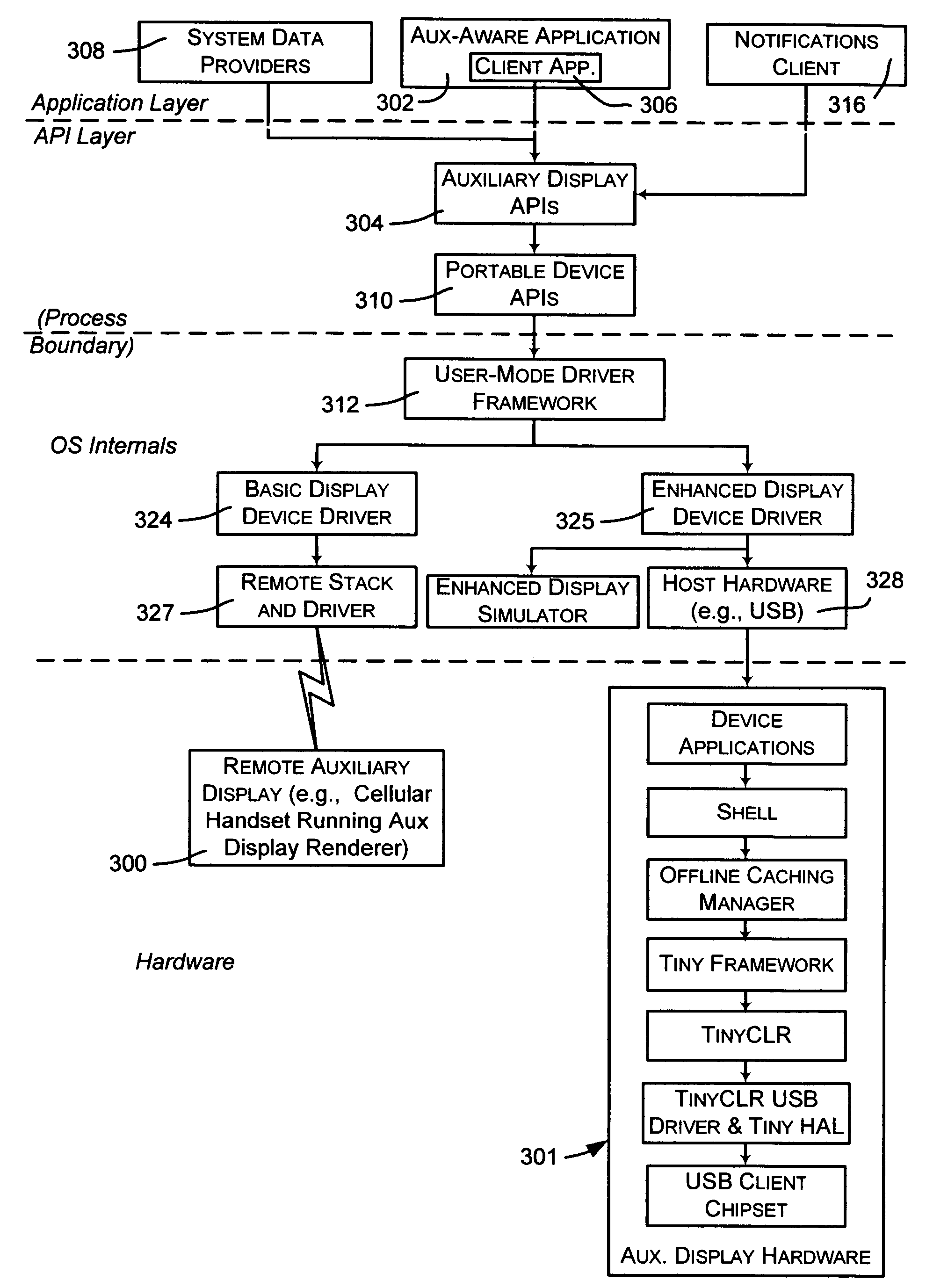
[0011]In addition to working with auxiliary displays such as mobile telephones and secondary computers, the present invention may be used to extend the ability of the main computer system to communicate with previously single-purpose devices, such as televisions, radios, other media players, digital image-based picture frames, clocks including watches and alarm clocks, and so forth. With some software and little or no hardware additions, such existing devices may easily expand their utility by allowing them to integrate with a main computer system. The platform is extensible in hardware and software to enable such scenarios. At the same time, the task of communicating with an auxiliary device from the perspective of independent software vendors is greatly simplified because application program code only needs to be written once to have it run on a wide variety of devices, with no additional work required to adapt the program for different auxiliary devices.

Problems solved by technology

Other devices are more limited, however, and may, for example, only provide a single line of text, lights, and / or audio.

Method used


Image

  • Method and system for exchanging data between computer systems and auxiliary displays
  • Method and system for exchanging data between computer systems and auxiliary displays
  • Method and system for exchanging data between computer systems and auxiliary displays

Examples


Embodiment Construction

Exemplary Operating Environment

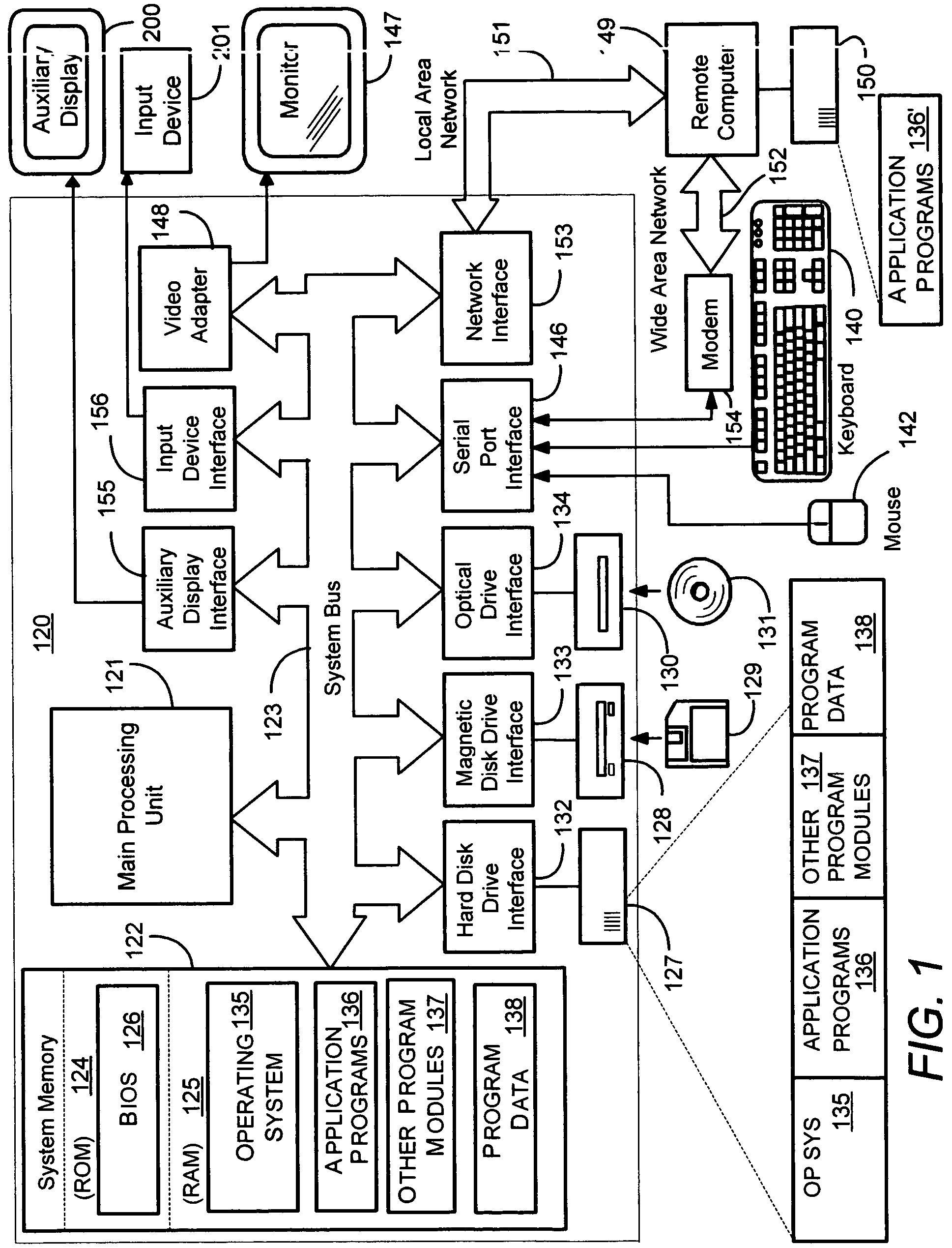
[0019]FIG. 1 is a block diagram representing a computing device 120 in the form of a personal computer system into which the present invention may be incorporated. Those skilled in the art will appreciate that the personal computer system 120 depicted in FIG. 1 is intended to be merely illustrative and that the present invention may be practiced with other computer system configurations, including hand-held devices, multi-processor systems, microprocessor-based or programmable consumer electronics, network PCs, minicomputers, mainframe computers, headless servers and the like. The invention may also be practiced in distributed computing environments where tasks are performed by remote processing devices that are linked through a communications network. In a distributed computing environment, program modules may be located in both local and remote memory storage devices.

[0020]The personal computer system 120 includes a processing unit 121, a system memo...


PUM


Abstract

Described is a system and method by which application programs running on a main computer system communicate with an auxiliary display device (such as a cell phone, pocket-sized computer, alarm clock, television, digital picture frame and so forth) to provide viewable information on the device, remote control capabilities, and notifications. Via API calls, programs provide information in the same format regardless of the device capabilities and / or the connection type. An auxiliary display platform converts the information into a format understood by a device driver, which then filters the information as desired for its particular hardware device before the information is communicated. Return communications return data such as status and user interaction with the displayed information. Software vendors may thus write code once to output information on auxiliary displays, while hardware manufacturers can have their devices work as auxiliary displays, with little or no modification to existing hardware.

Description

FIELD OF THE INVENTION[0001]The invention relates generally to computer systems, and more particularly to an improved system and method for communicating information between a computer system and an auxiliary device.BACKGROUND OF THE INVENTION[0002]U.S. patent application Ser. Nos. 10 / 429,930 and 10 / 429,932, now U.S. Pat. Nos. 7,240,228 and 7,221,331, respectively, are generally directed towards the concept of computer systems having auxiliary processing and auxiliary mechanisms that provide some auxiliary computing functionality. For example, a small LCD on the lid or side of a laptop computer can provide its owner with useful information, such as a meeting location and time, even when the main computer display is not easily visible, e.g., when a laptop computer's lid is closed and / or the main computer is powered down. Controls such as buttons may be provided to allow the user to interact with the auxiliary device to view different types of data, such as to scroll through appointme...

Claims


Application Information

Patent Timeline
Patent Type & Authority Patents(United States)
IPC IPC(8): G06F3/00G06F13/00G06F9/44G09G5/00
CPCG06F3/14G06F9/541G06F3/1438
Inventor RHOTEN, MATTHEW P.FULLER, ANDREW J.WYNN, ROGER H.BERNSTEIN, MICHAEL S.POLIVY, DANIEL J.
Owner MICROSOFT TECH LICENSING LLC
Learn More