Broadcasting service system using mobile communication terminal

Inactive Publication Date: 2009-12-15
LG ELECTRONICS INC
View PDF26 Cites 37 Cited by
  • Summary
  • Abstract
  • Description
  • Claims
  • Application Information

AI Technical Summary

Problems solved by technology

Organic combination or link between the conventional personal mobile communication system and digital television system for maximizing advantages of both systems is not acc

Method used


Image

  • Broadcasting service system using mobile communication terminal
  • Broadcasting service system using mobile communication terminal
  • Broadcasting service system using mobile communication terminal

Examples


Embodiment Construction

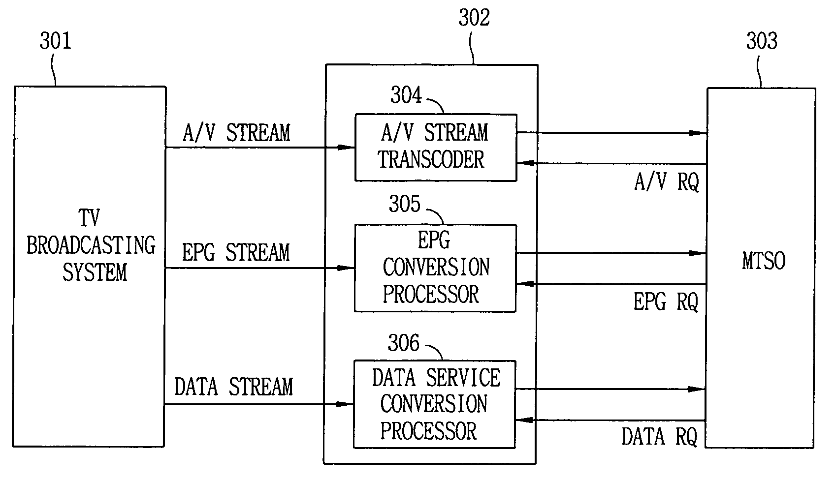
[0024]FIG. 1 is a schematic block diagram illustrating the structure of a broadcasting service system using a mobile communication terminal of the preferred embodiment of the present invention. As depicted in FIG. 1, a television broadcasting system 101 transmits a video and audio signal to a subscriber terminal 104 through a satellite network 102, a television broadcasting network 103 or a cable network (Cable). The subscriber terminal 104 receives the video and audio signal, and outputs an image and sound by decoding the video and audio signal.

[0025]Herein, the television broadcasting system 101 may be a moving picture and audio information broadcasting system, an analog television broadcasting system, a digital television broadcasting system, or other moving picture information broadcasting system.

[0026]The conventional analog broadcasting system includes a NTSC (National Television System Committee) broadcasting method, a PAL (Phase Alternation Line) broadcasting method, and a S...


PUM


Abstract

A system capable of receiving a television signal and telephone signal on a mobile communication terminal. In particular, the system is capable of displaying each television broadcast on a monitor of the mobile communication terminal by receiving the video and audio signal, decoding it, and outputting it to the monitor of the mobile communication terminal. In addition, the system can transmit an EPG (Electronic Program Guide) data corresponding to a subscriber request and a selected broadcasting program in real time.

Description

BACKGROUND OF THE INVENTION[0001]1. Field of the Invention[0002]The present invention relates to a system which is capable of receiving a broadcasting signal and a telephone signal, and watching and listening to them on a mobile communication terminal, and in particular to a system which is capable of receiving a video signal and an audio signal, decoding them, and displaying the decoded signals on the monitor of the mobile communication terminal.[0003]2. Description of the Prior Art[0004]Organic combination or link between the conventional personal mobile communication system and digital television system for maximizing advantages of both systems is not accomplished. In addition, in the digital television system, various additional information with high quality images are only provided to digital television sets. In other words, the conventional personal mobile communication system such as a cellular phone cannot transmit and receive video, audio and character information.SUMMARY O...

Claims


Application Information

Patent Timeline
IPC IPC(8): H04N5/445G06F13/00G06F3/00H04N7/16H04L12/28
CPCH04W4/18H04H20/24H04H20/06H04W4/06H04L12/28
Inventor PAIK, WOO HYUNKANG, BAE GUENPARK, TAE JUNLEE, SENG WHAN
Owner LG ELECTRONICS INC
Why Eureka
Try Eureka