
Structural support systems and methods to reinforce lintel support systems

a structural support system and lintel technology, applied in the direction of girders, building repairs, transoms, etc., can solve the problems of lintel technique, limited weight that can be supported by the horizontal lintel, and the distance required between vertical posts to ensure the effect of suppor

Active Publication Date: 2009-12-22
TROTTER WILLIAM CLAY
View PDF19 Cites 4 Cited by
  • Summary
  • Abstract
  • Description
  • Claims
  • Application Information

AI Technical Summary

Benefits of technology

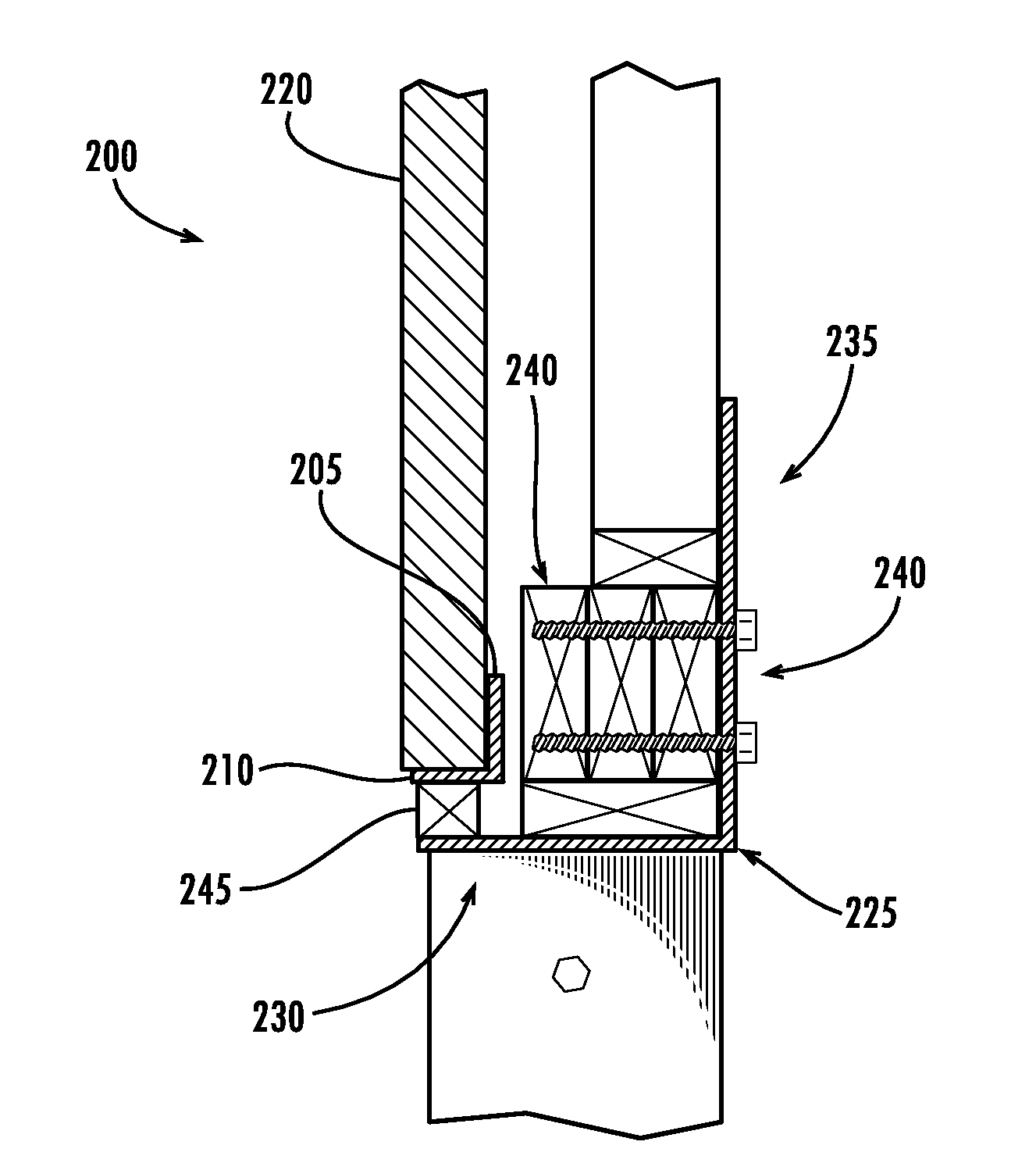
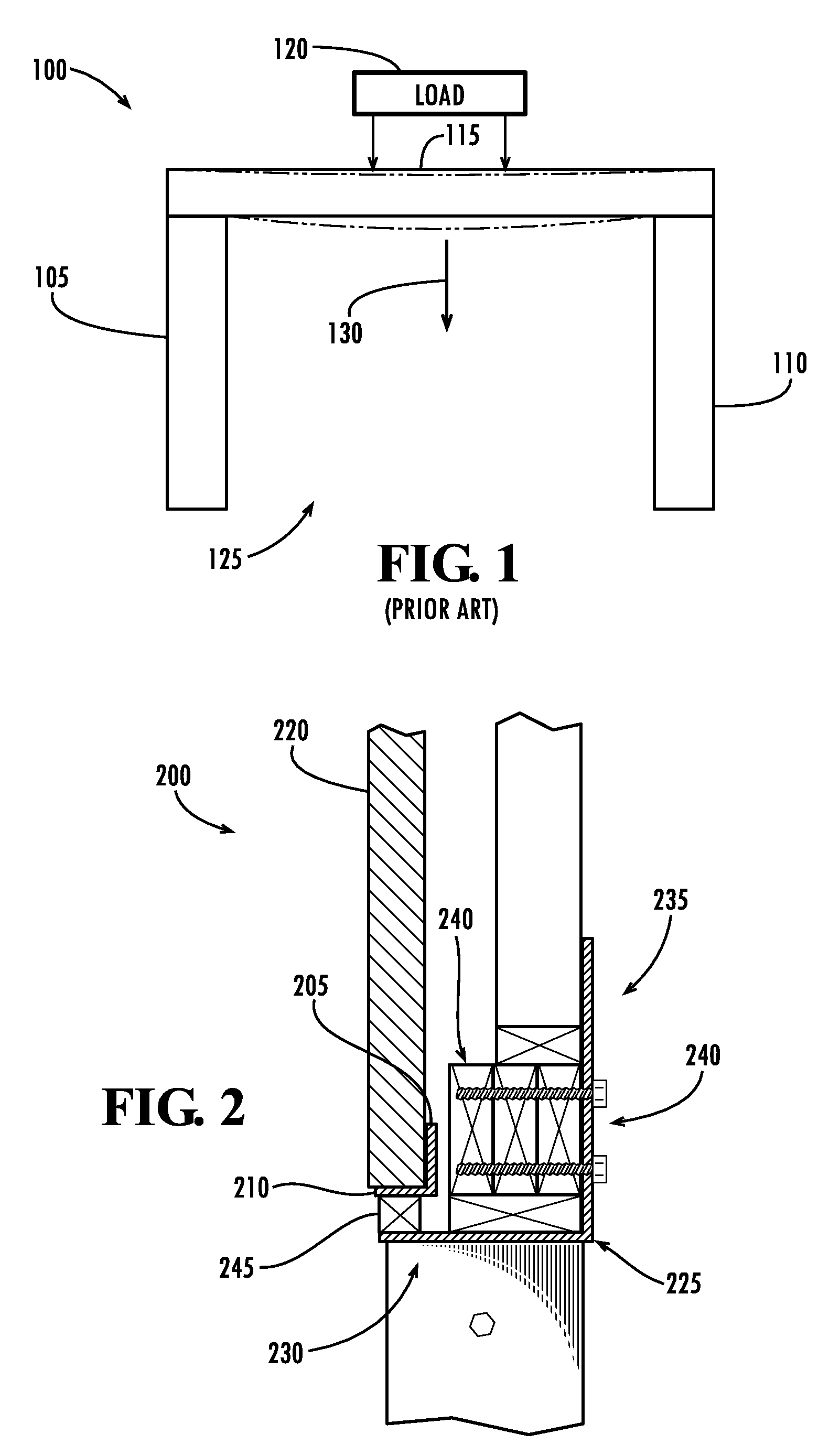
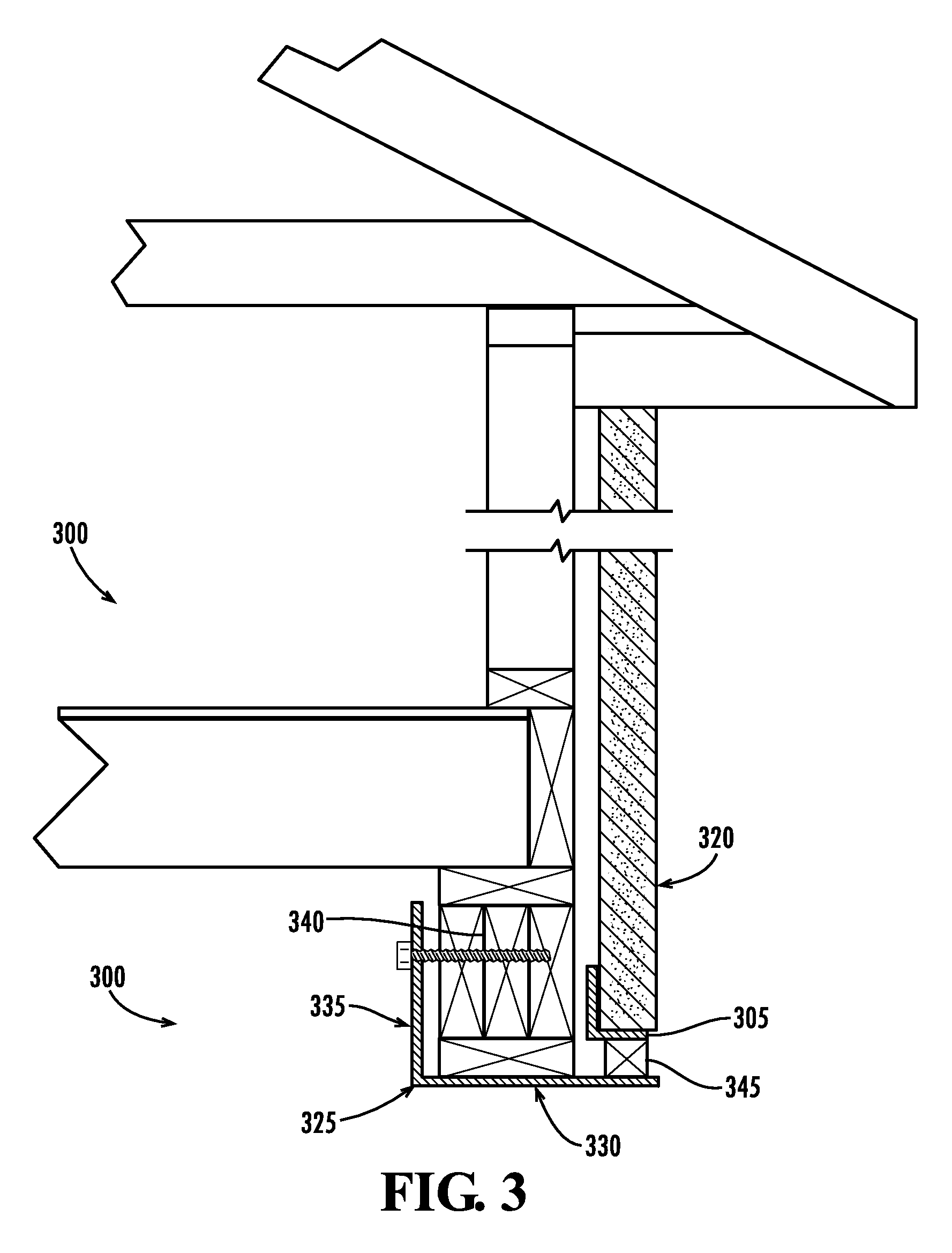
"The present invention provides a system to reinforce load bearing members used to support a load above an opening, such as a home car garage or window opening. The system includes an elongated reinforcing member that is placed beneath the load bearing member to support it. The reinforcing member has two portions: a first portion that is placed beneath the load bearing member and a second portion that extends in a normal direction from the first portion and is fixed in a static position to support the load bearing member. This system can provide additional strength and stability to the load bearing member, ensuring the safety and security of the load."

Problems solved by technology

While the post and lintel construction technique is widespread and used considerably, it does suffer from certain drawbacks.
For example, one drawback to the post and lintel technique is the limited weight that can be supported by the horizontal lintel and the distances required between vertical posts to ensure that the horizontal member is sufficiently supported.
Also, as homeowners modify home space above lintel supported openings (such as attic over garage bonus rooms) this increased load may be too much as an installed lintel may not be designed to carry such an increased load.
Another drawback is that the horizontal member can sag or develop an arch if not properly supported or if the post and lintel technique is not properly designed.
As one might imagine, failure of the horizontal lintel 115 can lead to disastrous results due to the load 120 collapsing the lintel 115 and possibly even harm those passing through openings supported by a structurally unsound lintel.
In addition, faulty lintels can cause damage to the surrounding structural or aesthetic components.
For example, faulty or sagging lintels used in home construction can cause surrounding bricks to crack, mortar joints to fail, stucco exteriors to develop stress cracks, and exterior siding to lose a plumb finish.
Other issues may also lead to a faulty post and lintel system.
For example, construction workers may not fully appreciate a load that a lintel will carry during use and therefore install a post and lintel system not capable of carrying a load.
Such an under appreciation of a future load can therefore cause failure of a lintel.
Issues such as appropriate sizing of components of a post and lintel system can lead to a faulty post and lintel support system, especially when a lintel is overspanned (e.g., not adequately supported by posts) or undersized.
Others who do not detect such problems, however, are usually forced to spend extensive resources for major renovation work.
While serving their respective purposes, the above conventional solutions have associated drawbacks.
This could prove troublesome if the additional vertical supports were accidentally knocked out of position; thus, this solution decreases the use of an opening.
This requirement creates extra demolition and installation work since both sides of the header must be accessed to install Parker's brace.
Also Parker's lintel support brace transfers load and stress to a header and at the same time does not increase the load carrying capability of the header.
In some instances, this may cause a header to fail.
In addition, Parker's brace is only applied as a spot relief and does not run the entire length of the lintel nor does Parker's brace add any additional vertical post support to the lintel.

Method used


Image

  • Structural support systems and methods to reinforce lintel support systems
  • Structural support systems and methods to reinforce lintel support systems
  • Structural support systems and methods to reinforce lintel support systems

Examples


Embodiment Construction

[0019]Referring now to the figures, wherein like reference numerals represent like parts throughout the several views, exemplary embodiments of the present invention will be described in detail. Throughout this description, various components may be identified as having specific values or parameters, however, these items are provided as exemplary embodiments. For example, it should be understood that while exemplary embodiments of the present invention are discussed herein with reference to home garage openings, embodiments of the present invention can be used to reinforce and support other load bearing members utilized in numerous other structural openings. In addition, embodiments of the present invention can be used to reinforce existing load carrying members or used during the construction of new load carrying members. Thus, the exemplary embodiments do not limit the various aspects and concepts of the present invention as many comparable parameters, sizes, ranges, and / or values...


PUM


Abstract

Structural support systems and methods are provided to reinforce lintel support systems. According to some embodiments, a reinforcement system to reinforce an elongated load bearing member having opposing ends and supporting a load can comprise an elongated reinforcing member having a first portion and a second portion. The first portion can be disposed beneath the load bearing member between the opposing ends of the load supporting member and have a length substantially equal to the length of the load bearing member. The second portion can have length greater than the first portion. Also, the second portion can extend in a substantially normal direction from the first portion and be spaced apart from the load bearing member. The second portion can be securedly fixed in a substantially static position to support the first portion disposed beneath the load bearing member. In one configuration, the second portion can be fixed to a header associated with a lintel support system. Other embodiments are also claimed and described.

Description

TECHNICAL FIELD[0001]The various embodiments of the present invention relate generally to structural support systems and methods, and more specifically, to systems and methods to reinforce the structural supporting systems of garages, windows, and other openings utilizing a lintel support structure.BACKGROUND[0002]The post and lintel construction technique (also called the post and beam technique) is commonly utilized when building homes and other such structures. This technique is a simple, yet effective construction technique and is thus used by many architects and builders to support a load above an opening. In the post and lintel technique, two vertical members (or the posts) support a horizontal member (or the lintel) at opposing ends of the horizontal member. The famous Stonehenge monument is a classical example of the post and lintel technique.[0003]The post and lintel technique is commonly used to support loads over door, garage, and window openings. For example, FIG. 1 illu...

Claims


Application Information

Patent Timeline
Patent Type & Authority Patents(United States)
IPC IPC(8): E04C3/02
CPCE04C3/02E04G23/0218E04C2003/023
Inventor TROTTER, WILLIAM CLAY
Owner TROTTER WILLIAM CLAY
Learn More