Rotary cutting machine with replaceable cutting teeth

Active Publication Date: 2009-12-22
QUADCO
View PDF73 Cites 36 Cited by
  • Summary
  • Abstract
  • Description
  • Claims
  • Application Information

AI Technical Summary

Problems solved by technology

Thus, when one cutting edge wears or becomes damaged and thus unsuitable for cutting, i.e. optimum cutting, the tooth in question can be removed from the holder and replaced back in place thereon with a different cutting edge in position for contacting the workpiece.

Method used


Image

  • Rotary cutting machine with replaceable cutting teeth
  • Rotary cutting machine with replaceable cutting teeth
  • Rotary cutting machine with replaceable cutting teeth

Examples


Embodiment Construction

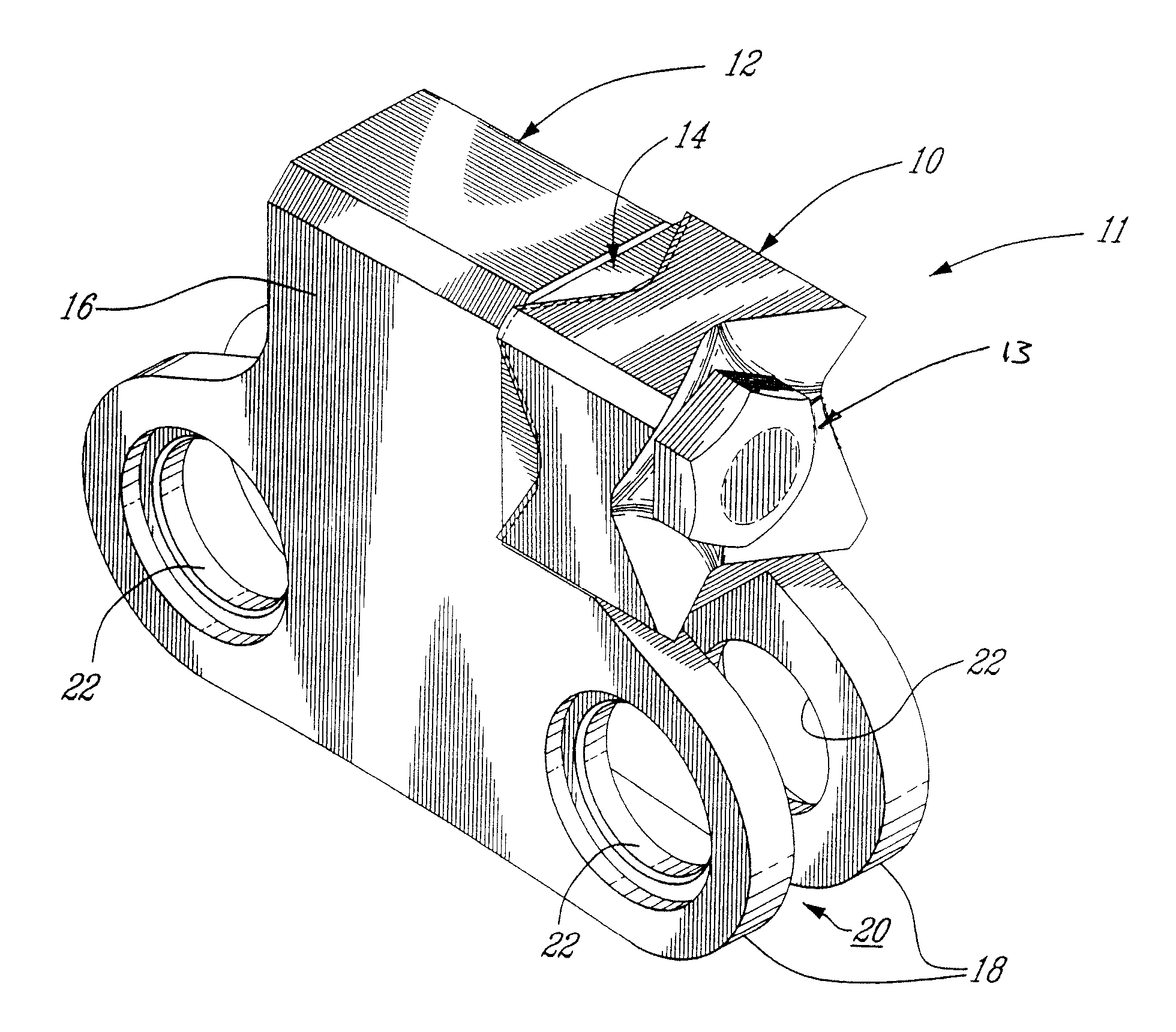
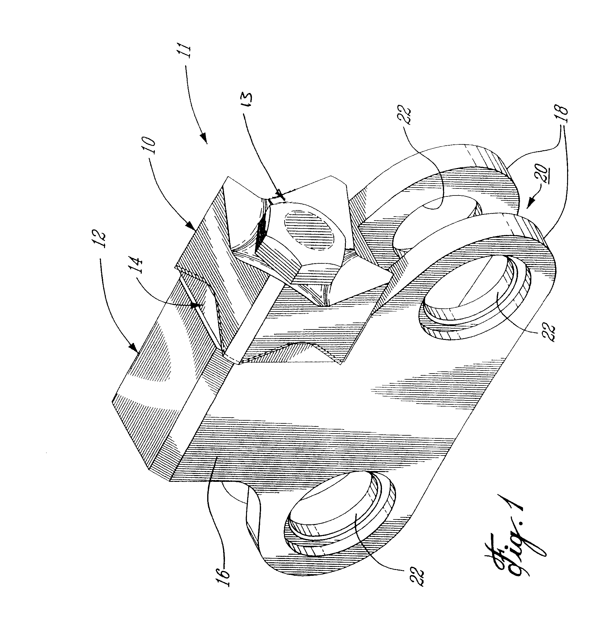
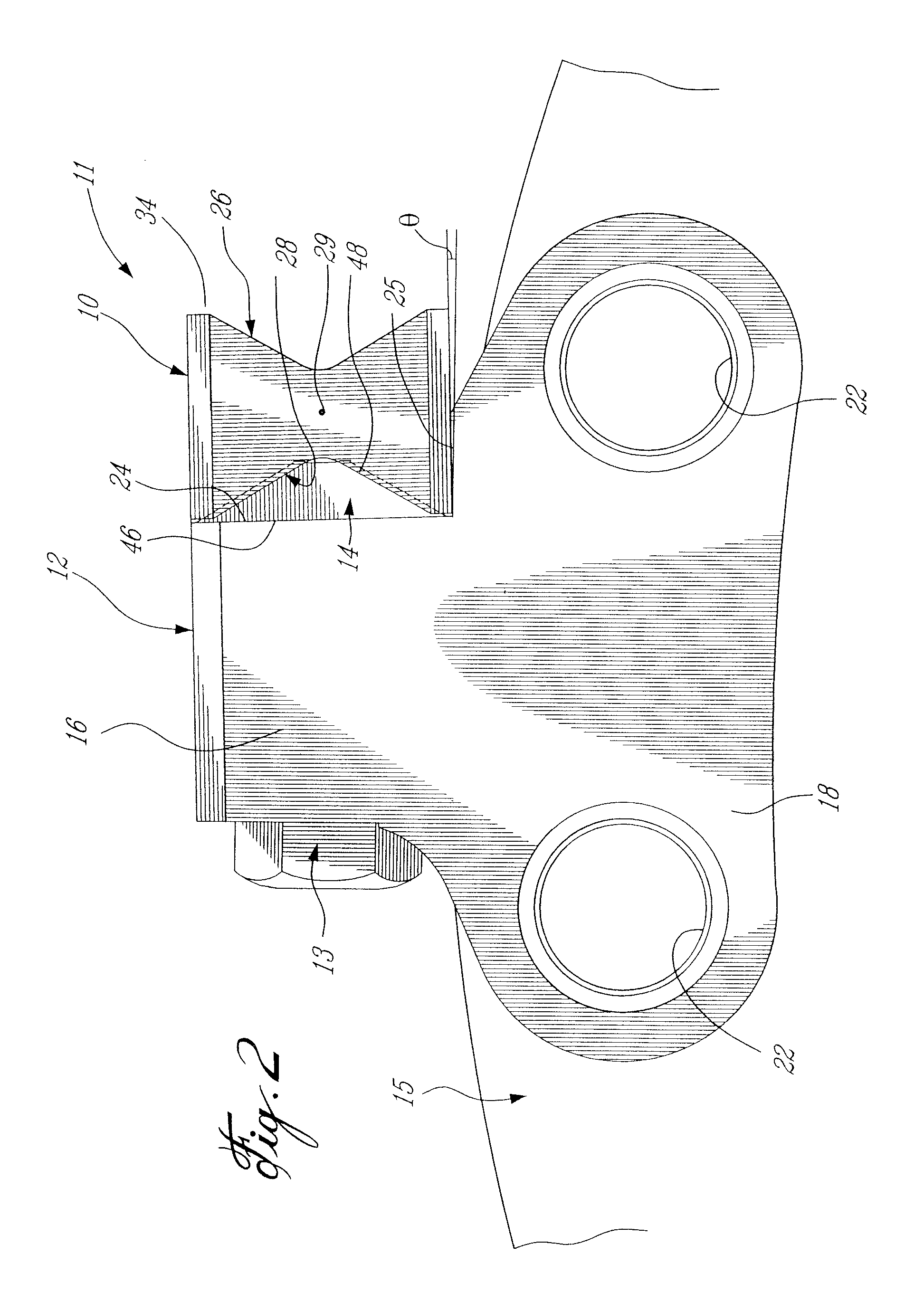
[0056]The term “saw tooth” is used herein to refer to a cutting implement or tooth for use, in at least one embodiment, in a rotary cutting machine for which replaceable saw teeth may be provided, such as a circular saw having a saw disk with such replaceable saw teeth mounted about the periphery thereof, either fixed directly thereto or through a holder. However, a cutting tooth in accordance with the present invention may be used in any cutting machine for which replaceable cutting teeth may be desired, and which can be used to cut any number of materials and / or products. Such a rotating cutting machine also includes brush mowers of the type having a rotating drum upon which a number of cutting teeth are fixed, and which are used to clear bushes, brush, and smaller trees, for example.

[0057]Referring first to the embodiment shown in FIGS. 1 to 5, a saw tooth assembly 11 which is adapted, in at least one application of the present invention, to be mounted about the periphery of a ci...


PUM


Abstract

A rotary cutting machine comprises a circular rotating element having a transverse axis of rotation and which is mounted to the rotary cutting machine for rotation about the axis of rotation. A plurality of cutting teeth are mounted to the circular rotating element at spaced apart locations about its circumferential periphery. The cutting teeth are reversible and removably fastened to the circular rotating element. Each cutting tooth includes opposed first and second cutting faces spaced apart by lateral surfaces extending therebetween. The first and second cutting faces define at least four of the cutting edges thereon, such that the cutting teeth are selectively mountable on the circular rotating element in any one of at least eight different positions, each of the positions providing a different one of the cutting edges in the operable cutting position.

Description

RELATED APPLICATIONS[0001]This application is a continuation-in-part of U.S. patent application Ser. No. 11 / 560,582 filed Nov. 16, 2006, which itself claims priority on U.S. Provisional Patent Application No. 60 / 736,832 filed Nov. 16, 2005, the entire specifications of both of which are incorporated herein by reference.TECHNICAL FIELD[0002]The present invention relates generally to a rotary cutting machine, for example a brush mower or cutter, a stump grinder, a shredder or grinder and the like, having replaceable cutting teeth engaged about a rotating element such as a disk, drum, shaft or the like.BACKGROUND[0003]Rotary cutting machines, particularly relatively large ones, are used in various applications which include, but are not limited to, felling trees and other natural plant growth in the forestry industry, clearing brush, grinding tree stumps, cutting rock and / or earth in the mining and construction industries, cutting up items such as used tires and other man-made products...

Claims


Application Information

Patent Timeline
Patent Type & Authority Patents(United States)
IPC IPC(8): B23D61/00B27B33/02
CPCB23D61/065B28D1/125B28D1/122B27B33/144Y10T83/9329Y10T83/9331
Inventor MACLENNAN, CHARLES D.PALFY, NICKRIOUX, DENISPERRON, ALAIN
Owner QUADCO
Why Eureka
Try Eureka