Spindle drive for a movable component, the spindle drive being drivable by a drive

a technology of movable components and spindles, which is applied in the direction of friction gearings, toothed gearings, door/window fittings, etc., can solve the problems of large structural space required for the drive of the spindle via a clutch, and the clutch is an elaborate and expensive component, etc., and achieves small structural space, simple structure, and easy manual movement.

Inactive Publication Date: 2009-12-22
STABILUS
View PDF4 Cites 8 Cited by
  • Summary
  • Abstract
  • Description
  • Claims
  • Application Information

AI Technical Summary

Benefits of technology

[0007]An object of the invention is to provide a spindle drive, of the type stated at the outset, which enables the movable component to be moved, both by the drive and with easy manual movement, and which requires a small structural space and is of a simple, inexpensive structure.
[0009]This design makes it possible to dispense with a clutch that would require a substantial structural space and elaborate structure. Only an anti-rotation element is required, this being easily mounted and requiring only a small installation space.
[0011]A compact construction is achieved where the intermediate element is a guide tube which surrounds the threaded spindle coaxially.
[0013]In this case, the driver or drivers can engage, at its / their free ends, in a ring groove of the transmission element, the ring groove being radially circumferential and open radially inwards. To increase the ease with which the component can be moved, the driver or drivers is / are preferably composed of a material which is of low friction as compared with the material of the transmission element, or it / they has / have a coating composed of a material which is of low friction as compared with the material of the transmission element.
[0014]It likewise serves to increase the ease of movement if the transmission element is mounted on a non-threaded portion of the threaded spindle so as to be capable of relative rotation via one or more bearings.
[0020]A simple structural space with a small space requirement results if a groove-free region of the guide tube carries a toothed wheel in which there engages either a pinion that can be rotatably driven by the drive or a pinion disposed on a brake shaft that can be arrested by the brake.

Problems solved by technology

In this case, driving of the spindle via a clutch requires a large amount of structural space.
Moreover, the clutch is an elaborate and expensive component.

Method used


Image

  • Spindle drive for a movable component, the spindle drive being drivable by a drive
  • Spindle drive for a movable component, the spindle drive being drivable by a drive
  • Spindle drive for a movable component, the spindle drive being drivable by a drive

Examples


Embodiment Construction

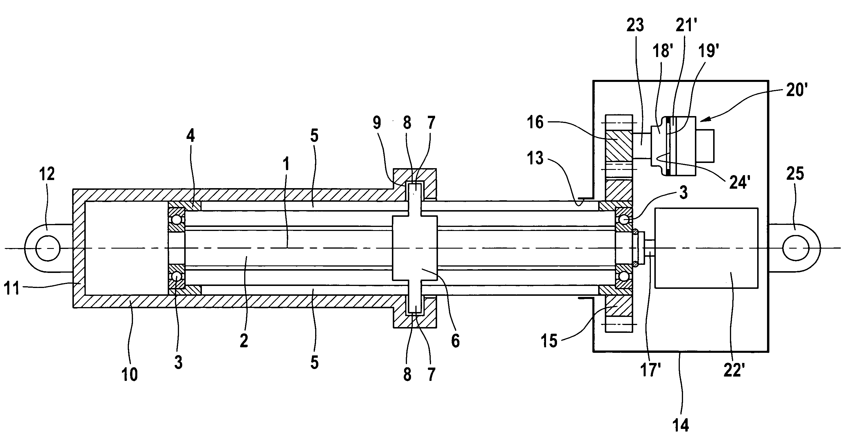
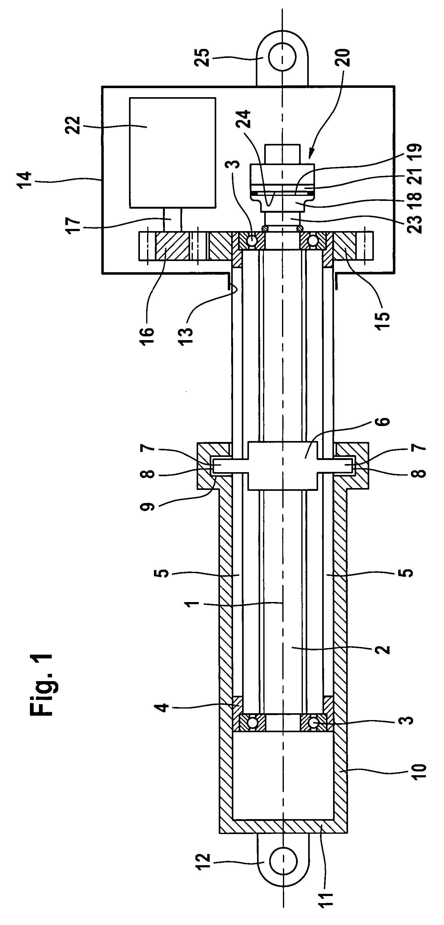
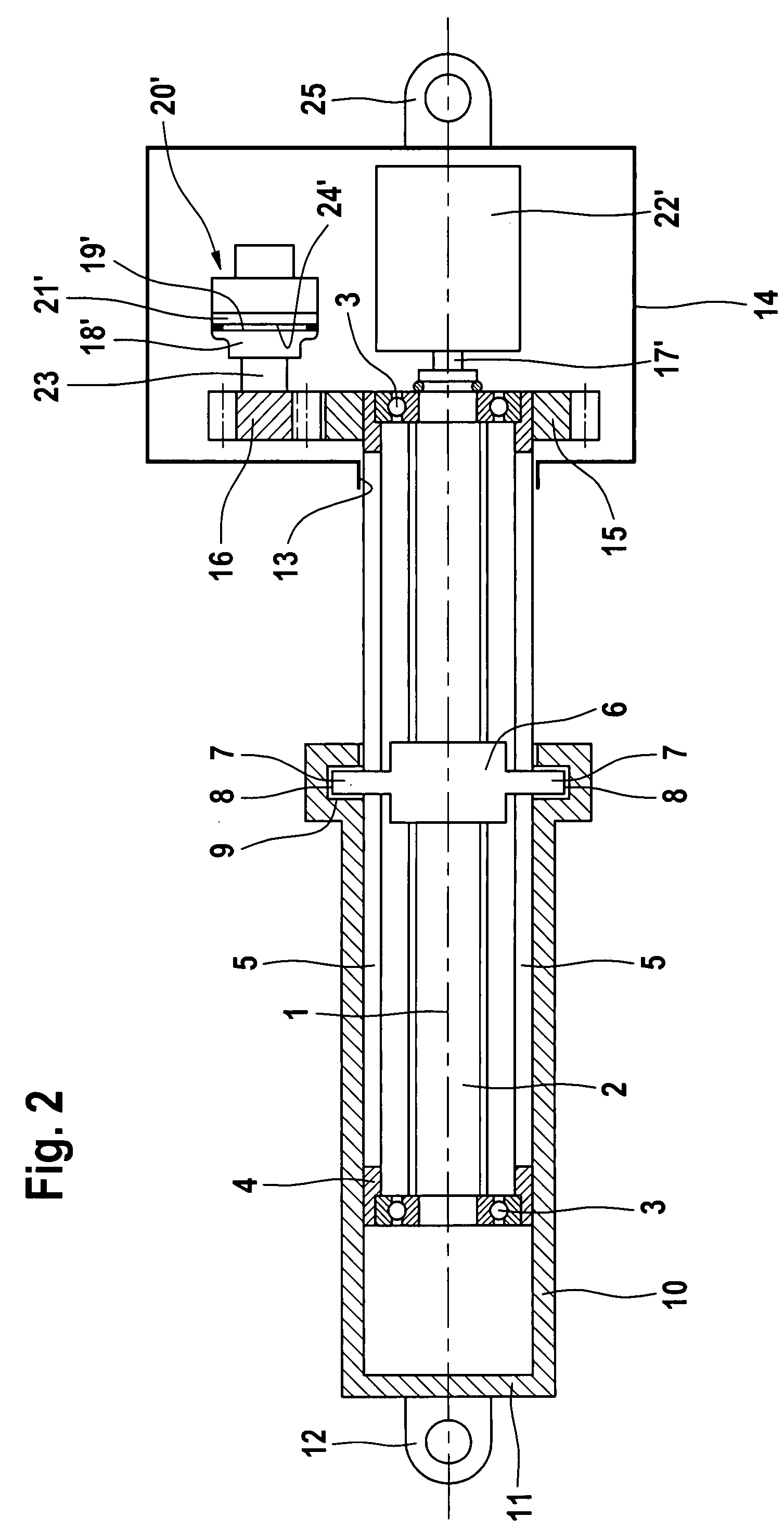
[0029]The spindle drives represented have a threaded spindle 2, which is rotatable about a spindle axis 1 and on both ends of which there is respectively disposed an inner race of a rolling bearing 3. A guide tube 4, which surrounds the threaded spindle coaxially at a distance, is disposed on the outer races of the rolling bearings 3, such that the threaded spindle 2 and the guide tube 4 can rotate freely relative to one another.

[0030]Longitudinal slots 5 are realized diametrically opposite each other in the guide tube 4, these slots extending over the length of the positioning travel of a spindle nut 6 disposed in a non-self-locking manner on the thread of the threaded spindle 2.

[0031]The spindle nut 6 has two radial drivers 7, which project radially through the longitudinal slots 5 and whose free ends 8 project into a ring groove 9 of a transmission tube 10 which is guided so as to be axially displaceable on the outer circumferential surface of the guide tube 4. The radially circu...


PUM


Abstract

A spindle drive for a movable component includes a threaded spindle which is rotatable about a spindle axis; a spindle nut which engages the threaded spindle; and a transmission element which can be connected to the movable component, the transmission element being fixed against rotation about the spindle axis and being axially drivable by rotation of the spindle nut. An intermediate element, which is fixed against rotation relative to the spindle nut, extends axially with respect to the threaded spindle and is rotatable relative to the threaded spindle. A drive is connected to rotate one of the intermediate element and the threaded spindle; and the other of the intermediate element and the threaded spindle can be fixed against rotation.

Description

BACKGROUND OF THE INVENTION[0001]1. Field of the Invention[0002]The invention relates to a spindle drive for a movable component, in particular for a component that can be swiveled about a swivel axis. The spindle drive is drivable by a drive and includes a threaded spindle which is rotatable about its spindle axis and on which there is disposed, in a non-self-locking manner, a spindle nut by which a transmission element that is connected to the component can be driven so as to be movable axially relative to the spindle axis. The transmission element, secured in respect of rotation about the spindle axis, is connected to the swiveling component.[0003]2. Description of the Related Art[0004]Known in the art, in the case of such a spindle drive for an automatically actuated vehicle door, is the practice of using an electric-motor drive for rotatably driving the threaded spindle via a gearing and a disconnectable clutch.[0005]Manual application of force to the vehicle door can be detect...

Claims


Application Information

Patent Timeline
Patent Type & Authority Patents(United States)
IPC IPC(8): F16H27/02
CPCE05F15/622F16H25/20E05Y2201/21E05Y2201/232E05Y2201/246E05Y2201/26E05Y2201/266E05Y2201/462E05Y2201/72E05Y2201/726E05Y2800/11F16H2025/2071F16H2025/2081E05Y2900/531E05Y2900/546Y10T74/18672Y10T74/18704Y10T74/18696E05Y2201/22
Inventor FRIEB-PREIS, TIMOKLEINMANN, MICHAEL
Owner STABILUS
Why Eureka
Try Eureka