Release handle with integrated inertia locking mechanism

a technology of inertia locking and release handle, which is applied in the direction of carpet fasteners, mechanical apparatus, lock applications, etc., can solve the problems of occupying a large amount of package space, occupying a large amount of counter-mass and associated components, and occupying a large amount of spa

Active Publication Date: 2009-12-22
ILLINOIS TOOL WORKS INC
View PDF5 Cites 41 Cited by
  • Summary
  • Abstract
  • Description
  • Claims
  • Application Information

AI Technical Summary

Benefits of technology

[0006]The present invention is directed to a release handle having an integrated inertia locking mechanism that addresses the above-mentioned limitations with known release handle protection systems. The invention is particularly beneficial in acceleration events, such as a multiple axis crash, by counteracting the forces of inertia caused by such crash. In an exemplary aspect of the invention, the integrated inertia locking mechanism will prevent the latch mechanism, which releases the door, from releasing and the door opening during a multiple axis crash. After the crash, or when the crash force is removed, the integrated inertia locking mechanism of the invention will allow the latch mechanism to function normally, thereby permitting the door to be opened and the occupants to exit from the vehicle.

Problems solved by technology

These known systems have certain limitations and drawbacks.
One such limitation is that the counter-mass and associated components require a significant amount of space, known as package space.
Another significant limitation is that counter-mass protected systems only perform up to a predetermined acceleration force.
If the forces during a crash exceed the predetermined acceleration, the counter-mass will no longer prevent the handle from opening and actuating the latch.
Yet another limitation is that counter-mass protected systems do not perform as well when the accelerations occur in multiple axes.
In some instances, forces on the counter-mass due to acceleration may cause the counter-mass to react in a manner that is counter productive to the protection of the handle.

Method used


Image

  • Release handle with integrated inertia locking mechanism
  • Release handle with integrated inertia locking mechanism
  • Release handle with integrated inertia locking mechanism

Examples


Embodiment Construction

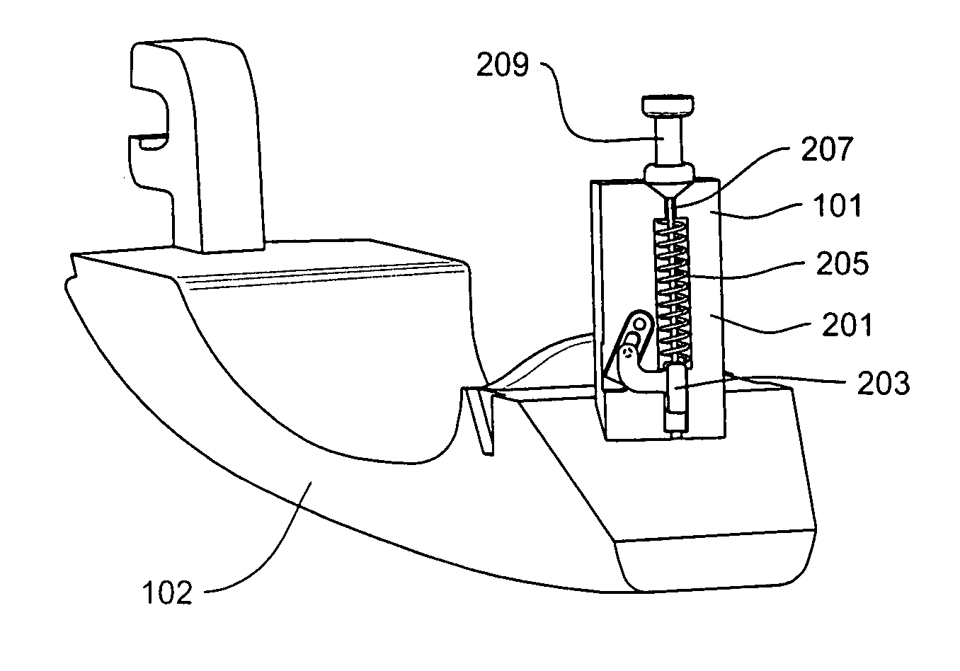
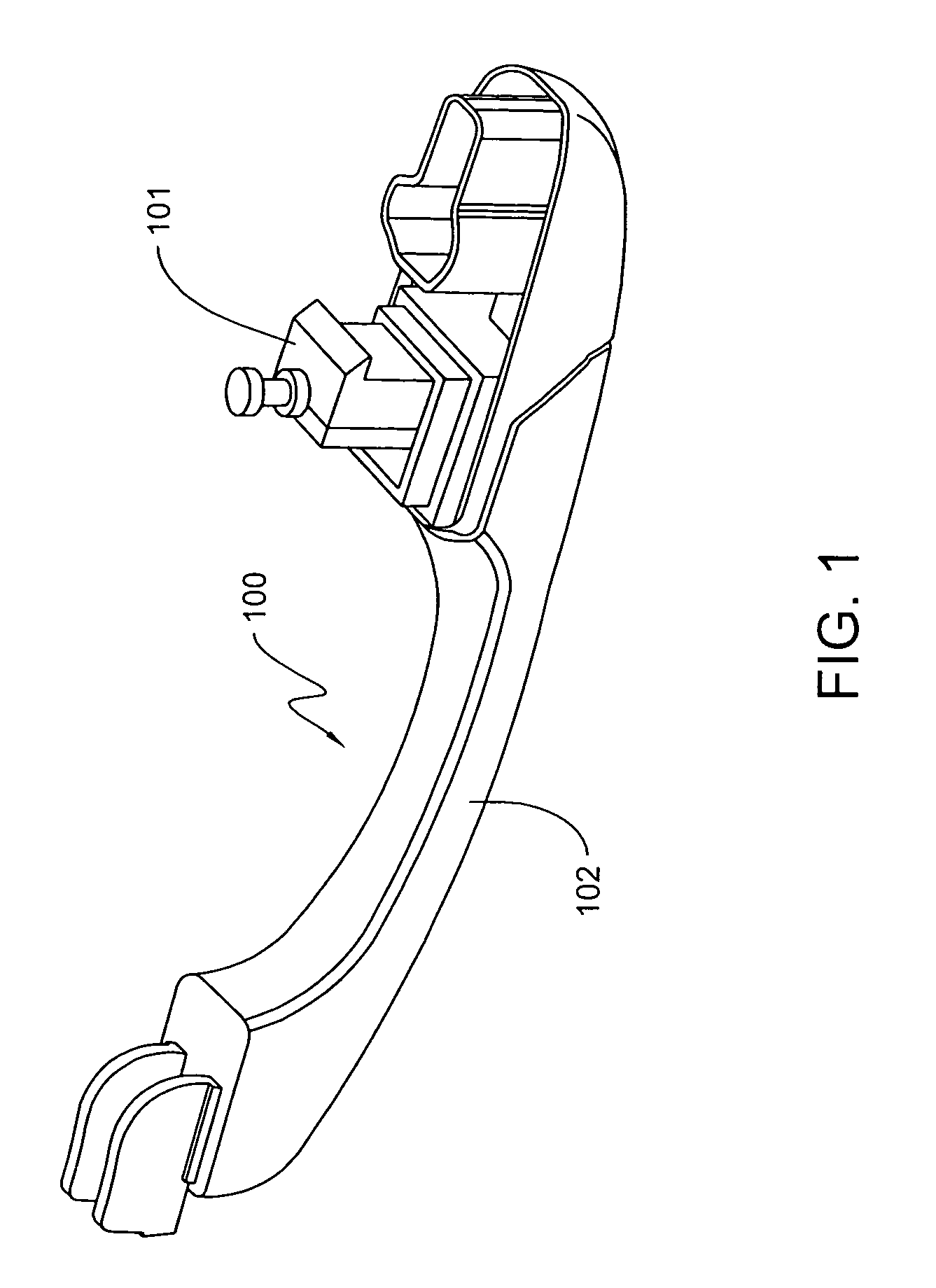
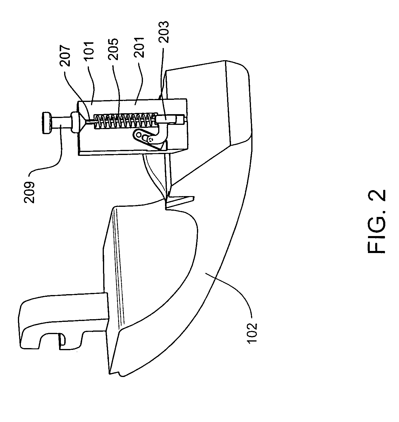
[0015]The present invention is directed to an inertia locking mechanism that may be used in any vehicle door handle assembly to counteract forces of acceleration or inertia caused by vehicle crashes, including multiple axis vehicle crashes. Referring to FIG. 1, an exemplary pull-style door handle assembly 100 is depicted that includes an inertia locking assembly 101, according to an embodiment of the invention, and a door handle 102. The inertia locking assembly 101 may be incorporated into a current production pull-style door handle with minimal or no changes to the surrounding environment, may be incorporated into a specially-designed door handle, or may be incorporated into any other known door handle. The inertia locking assembly 101 may be fully integrated into the handle component while not affecting or impeding the normal function of the handle component. The inertia locking assembly will take up significantly less space than other known protective devices.

[0016]In an exempla...


PUM


Abstract

An integrated inertia locking mechanism may be incorporated with a door handle assembly and is particularly beneficial in acceleration events, such as a multiple axis crash, by counteracting the forces of inertia caused by such crash. In an exemplary aspect, the integrated inertia locking mechanism will prevent the door latch mechanism, which releases the door, from releasing and the door opening during a multiple axis crash. After the crash, or when the crash force is removed, the integrated inertia locking mechanism will allow the latch mechanism to function normally, thereby permitting the door to be opened and the occupants to exit from the vehicle.

Description

FIELD OF THE INVENTION[0001]The present invention relates generally to a mechanism that resists the unlatching of a door of a vehicle if the vehicle is involved in a crash.BACKGROUND OF THE INVENTION[0002]There is a current trend in the vehicle manufacturing industry to equip vehicles with doors having pull-style release handles. A pull-style release handle is a handle that can be actuated by the operator by simply pulling in one direction, typically outward. Pull-style handles are replacing the previously used push button release and lift-style handles. A push button release handle includes a button that the operator pushes to unlatch and thus open the vehicle door. A lift-style handle is one that is actuated by lifting a pivoting mechanism both outward and upward to open the door.[0003]Vehicle door release systems, such as release handles, must meet certain safety and performance requirements particularly when subjected to high acceleration events, such as a vehicle crash. These r...

Claims


Application Information

Patent Timeline
Patent Type & Authority Patents(United States)
IPC IPC(8): E05B3/00E05B65/10
CPCE05B85/16E05B77/06Y10S292/22Y10T292/1002Y10T292/57
Inventor RODAWOLD, JR., JOSEPH L.GURTATOWSKI, CRAIG W.
Owner ILLINOIS TOOL WORKS INC
Why Eureka
Try Eureka