Spinal implant with biologic sponge

a sponge and spine technology, applied in the field of spinal implants, can solve the problems of changing the structure of the spine, the change of the disc, the pain of the back, etc., and achieve the effect of improving the resistance to compression forces, ensuring and effective implantation within the spine of the patien

Inactive Publication Date: 2008-12-11
CENTRA FUSE
View PDF38 Cites 50 Cited by
  • Summary
  • Abstract
  • Description
  • Claims
  • Application Information

AI Technical Summary

Benefits of technology

[0007]The present invention provides an intervertebral prosthesis having desirable geometries and characteristics for achieving secure and effective implantation within a patient's spine. In particular, a spinal prosthesis is provided generally defining a first wall, a second wall, and sidewalls extending from the first wall to the second wall. The spinal prosthesis may further define an upper surface and a lower surface, each of which may extend across a substantial portion of the body of the prosthesis. The spinal p...

Problems solved by technology

Disease, advancing age, and trauma can lead to changes in various bones, discs, joints, and ligaments of the body....

Method used


Image

  • Spinal implant with biologic sponge
  • Spinal implant with biologic sponge
  • Spinal implant with biologic sponge

Examples


Embodiment Construction

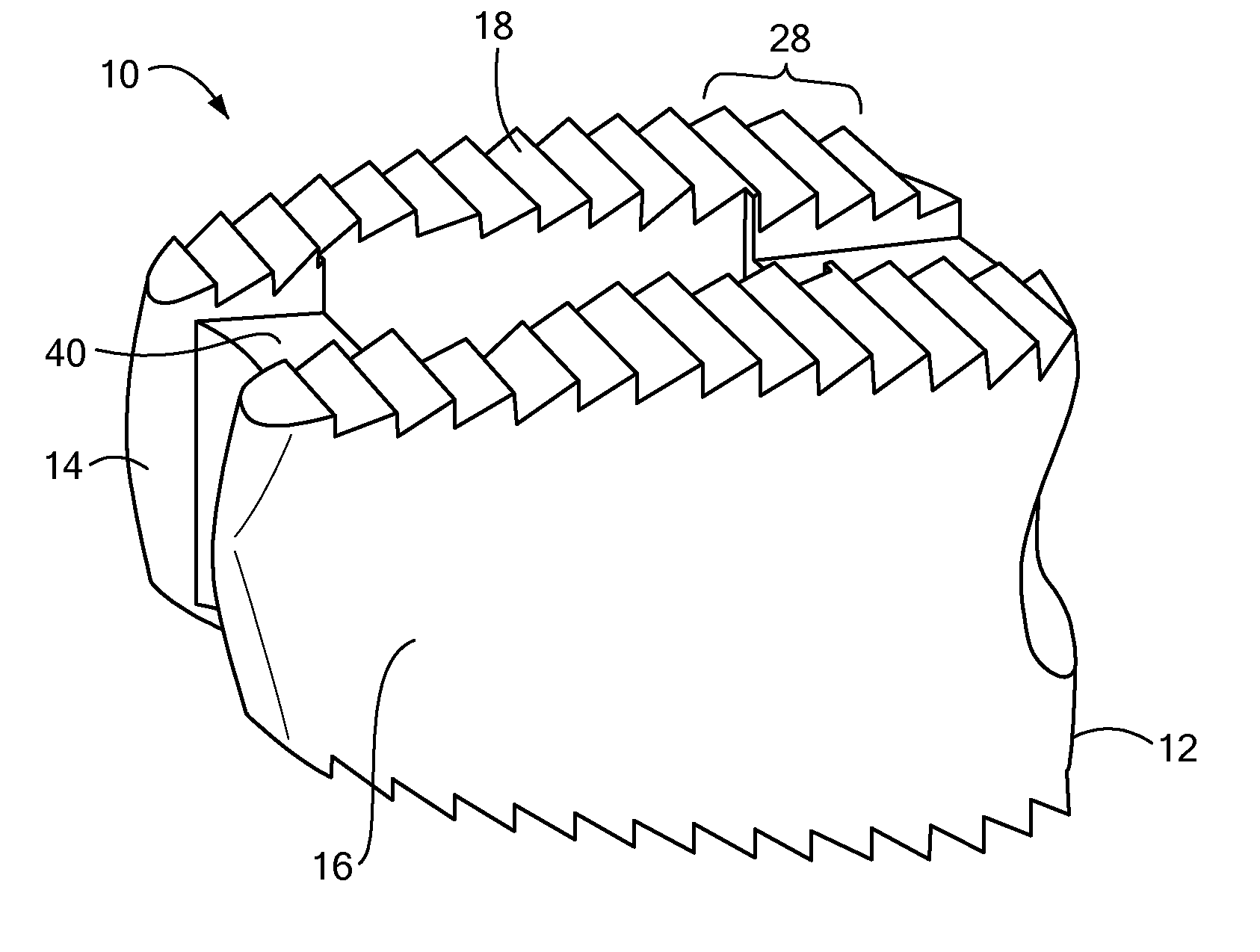
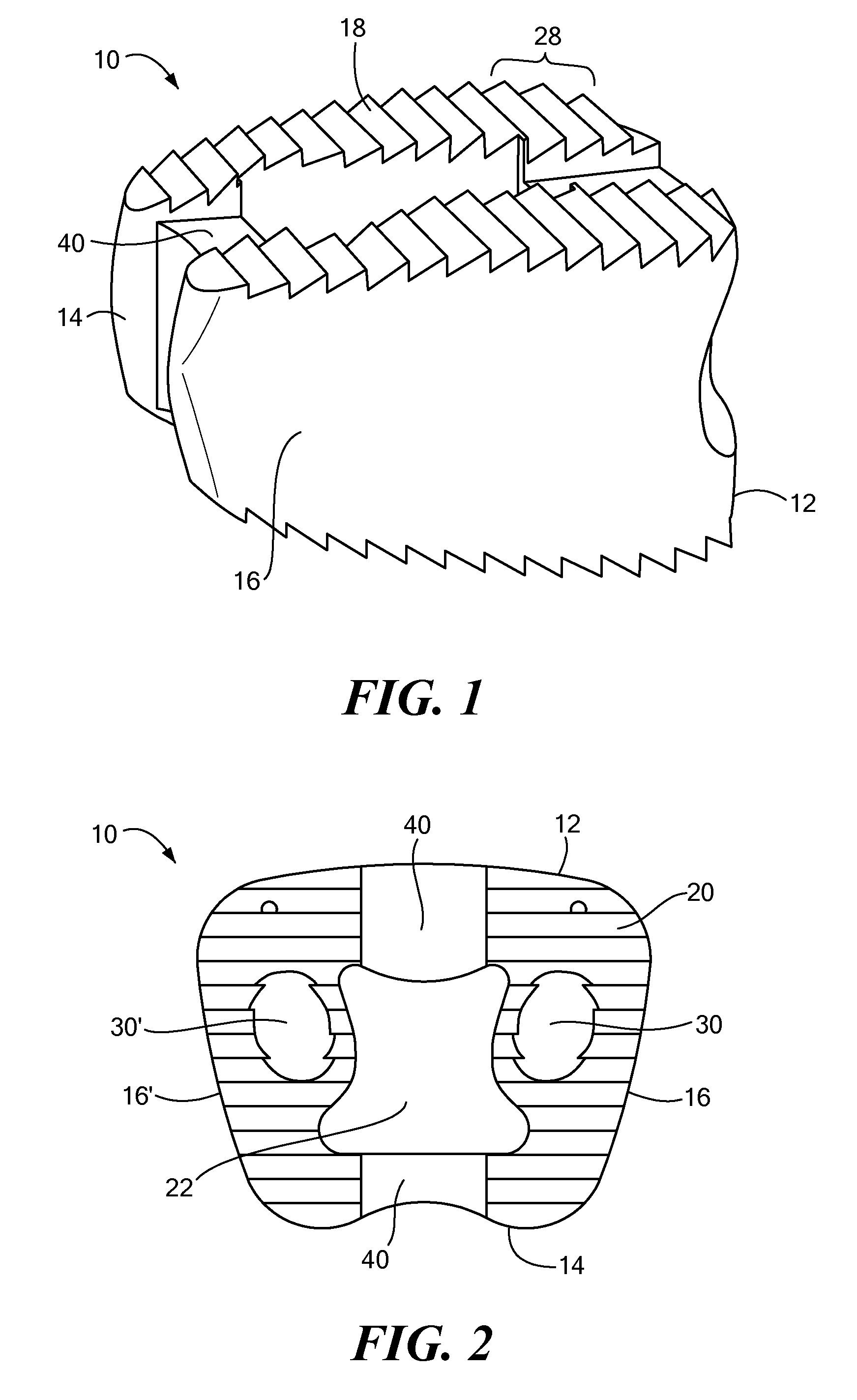
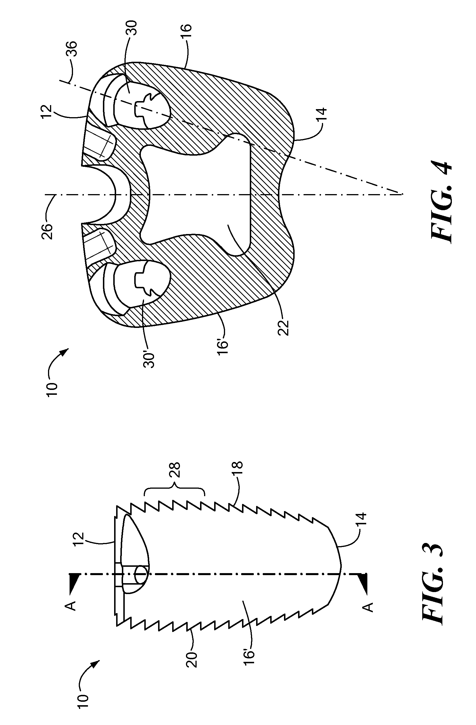
[0036]The present invention provides a system and method for repairing a diseased and / or damaged intervertebral disc or a portion thereof. Now referring to FIGS. 1-8, in particular, a spinal prosthesis 10 is provided, where the spinal prosthesis 10 may include a prosthesis body generally defining a first wall 12, a second wall 14, and sidewalls 16,16′ extending from the first wall 12 to the second wall 14. The second wall 14 may be curved or rounded to reduce friction and thereby ease insertion of the spinal implant into a portion of the spinal column. The spinal prosthesis 10 may further define an upper surface 18 and a lower surface 20, each of which may extend across a substantial portion of the body of the prosthesis. In addition, an aperture 22 may extend through a portion of the prosthesis from the upper surface 18 to the lower surface 20, where the aperture 22 may provide a path for bone growth and / or may allow for the addition of therapeutic materials within a portion of the...


PUM


Abstract

The present invention provides an intervertebral prosthesis generally defining a first wall, a second wall, sidewalls extending from the first wall to the second wall, and an upper surface and a lower surface. One or more passages may be included providing for an affixation element, to be inserted therethrough. The passages may each include a first portion for receiving a head or tip of an affixation element, and a second portion of a smaller diameter, where a substantial amount of the second portion of the passage located above or below a midline of the prosthesis. One or more openings may also be provided on the spinal prosthesis for coupling the prosthesis to a surgical tool, and the upper and lower surfaces of the prosthesis may include a depression or portion void of any teeth for the insertion of the prosthesis where a distraction tool is situated about the surgical site.

Description

CROSS-REFERENCE TO RELATED APPLICATION[0001]This application is a continuation-in-part-of pending patent application Ser. No. 11 / 732,137, filed Apr. 02, 2007, entitled SPINAL IMPLANT SYSTEM, the entirety of which is incorporated herein by reference.STATEMENT REGARDING FEDERALLY SPONSORED RESEARCH OR DEVELOPMENT[0002]n / aFIELD OF THE INVENTION[0003]The present invention relates to a method and system for replacing diseased and / or damaged intervertebral discs, and in particular, provides an artificial intervertebral disc prosthesis.BACKGROUND OF THE INVENTION[0004]Disease, advancing age, and trauma can lead to changes in various bones, discs, joints, and ligaments of the body. Some changes and trauma often manifest themselves in the form of damage or degeneration to a spinal disc or portion thereof. Such conditions often lead to chronic back pain, which can range from mild discomfort to severe, debilitating conditions. Treatment for degeneration and / or disease may include spinal fusion...

Claims


Application Information

Patent Timeline
IPC IPC(8): A61F2/44A61B17/08A61F2/02
CPCA61B17/86A61F2/30965A61F2/4455A61F2/447A61F2/4611A61F2/4684A61F2002/2835A61F2002/30136A61F2002/30677A61F2002/30772A61F2002/30774A61F2002/30787A61F2002/3082A61F2002/30904A61F2002/4629A61F2230/0004A61F2310/00293
Inventor HANSEN, ERICHAY, JAMES SCOTT
Owner CENTRA FUSE
Why Eureka
Try Eureka