Illuminated electrical center

a technology of illumination and electrical centers, applied in the direction of lighting and heating apparatus, lighting support devices, coupling device connections, etc., can solve the problems of consuming significant current, affecting the service life of the lamp, so as to achieve the effect of long service li

Inactive Publication Date: 2009-12-22
APTIV TECH LTD
View PDF7 Cites 163 Cited by
  • Summary
  • Abstract
  • Description
  • Claims
  • Application Information

AI Technical Summary

Benefits of technology

[0006]Electrical centers equipped with light-emitting diodes help service providers see the center when providing service; and they do so while consuming small amounts of electrical current and providing a long service life. Along with those benefits, electrical centers using light-emitting diodes may also provide a more pleasing aesthetic style than previous electrical centers.

Problems solved by technology

This can be impracticable because typically the service provider does not carry a portable light source.
Even when using a portable light source, such as a flashlight, the user must hold the source with one hand while performing service, which can be tiresome and awkward.
Incandescent light bulbs have been used for illumination, but they have some limitations.
Bulbs are somewhat fragile.
They consume significant amounts of current.
They generate heat, and are frequently too bulky for mounting in a streamlined electrical center design.

Method used


Image

  • Illuminated electrical center
  • Illuminated electrical center
  • Illuminated electrical center

Examples


Embodiment Construction

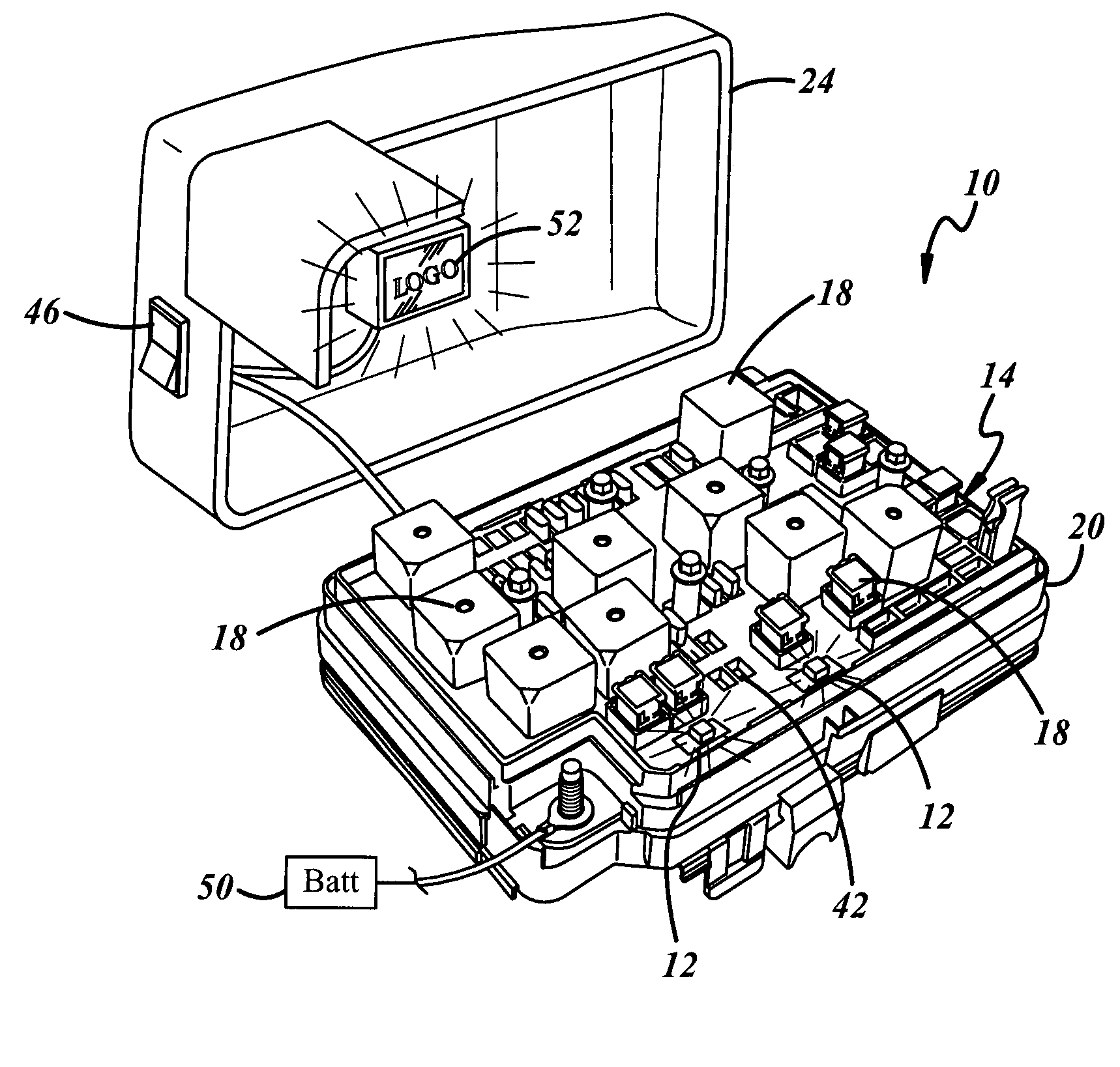
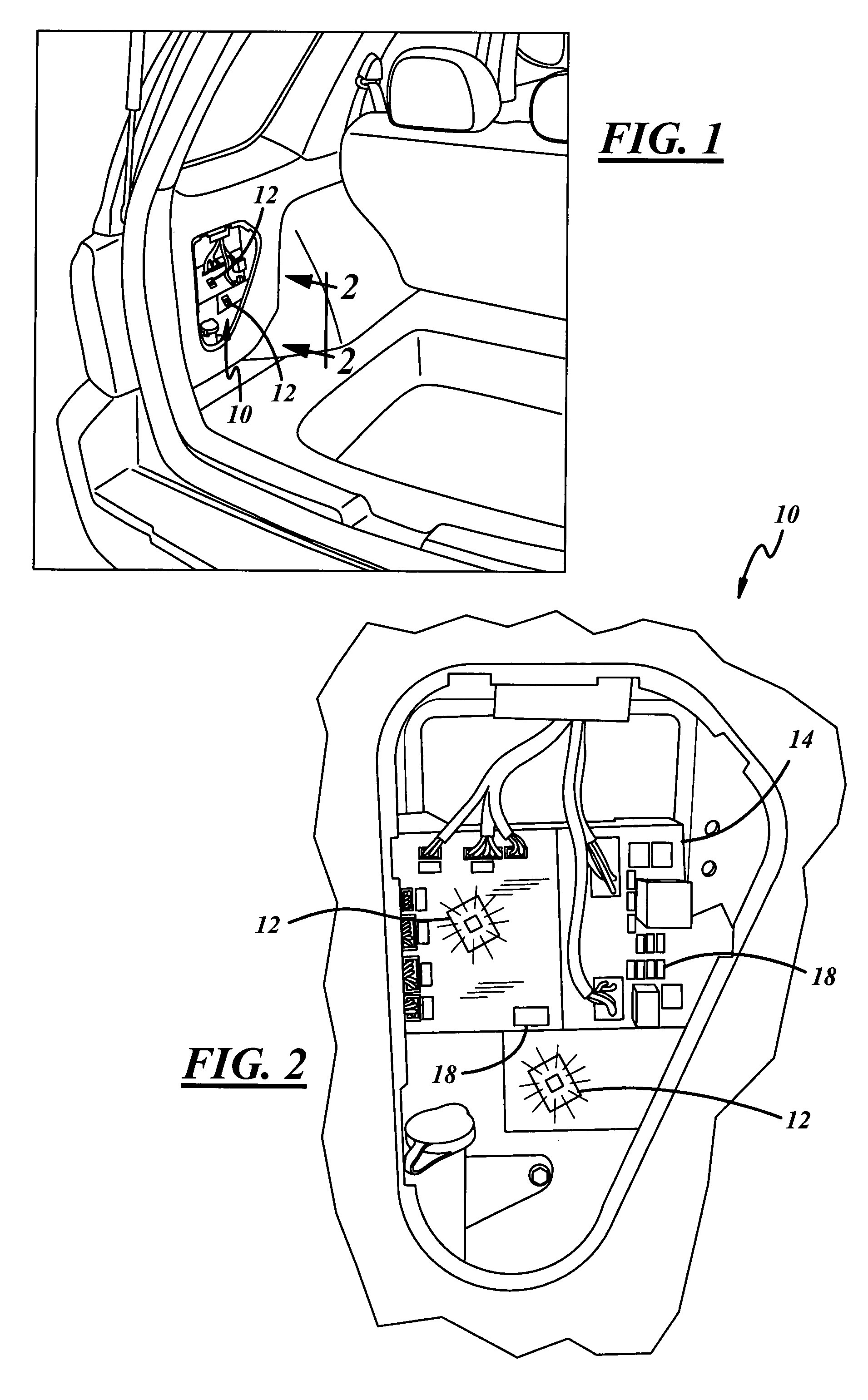
[0014]Referring in more detail to the drawings, FIGS. 1 and 2 illustrate an implementation of an electrical center assembly generally shown at 10 using a light-emitting diode 12 for illumination. FIGS. 1 and 2 show the electrical center 10 as it may be mounted in a vehicle. In this implementation, the electrical center 10 is hidden behind an automotive interior panel, but the electrical center 10 may also be mounted under the hood of a vehicle or in any other location where the electrical center assembly 10 may function.

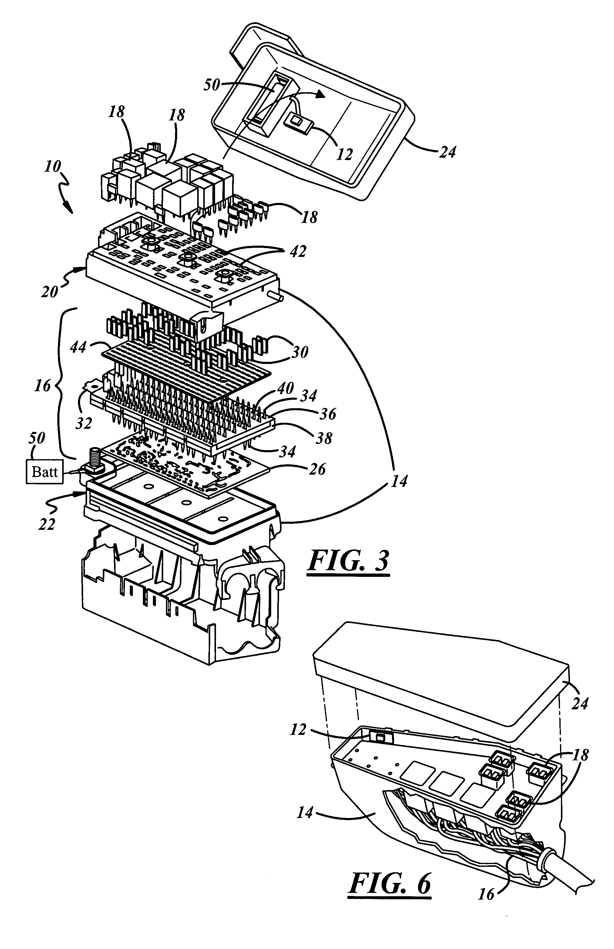
[0015]Turning to an implementation shown in FIG. 3, the electrical center assembly generally shown at 10 uses a light-emitting diode 12 for illumination. This implementation includes a housing generally indicated at 14 that carries an electrical conducting link generally indicated at 16, removable electrical components 18 and a light-emitting diode 12 for illuminating the electrical center 10. Other names are sometimes used to describe an electrical center 10. For ex...


PUM


Abstract

An electrical center assembly used in a vehicle provides ambient light to the assembly and the area around the assembly using a light-emitting diode. The electrical center assembly generally includes a housing, an electrically conducting link, removable electrical components and at least one light-emitting diode for illuminating the electrical center.

Description

BACKGROUND OF THE INVENTION[0001]This invention relates generally to electrical centers and more specifically to the illumination of electrical centers.[0002]Electrical centers provide electrical current flow to electrical components using a common power source and are well known in the art. The centers are mounted in a variety of locations in and on a vehicle. Often, the electrical centers are mounted in dark locations; and so when it is necessary to service the centers, the user must provide illumination with a portable light source. This can be impracticable because typically the service provider does not carry a portable light source. Even when using a portable light source, such as a flashlight, the user must hold the source with one hand while performing service, which can be tiresome and awkward. Incandescent light bulbs have been used for illumination, but they have some limitations. Bulbs are somewhat fragile. They consume significant amounts of current. They generate heat,...

Claims


Application Information

Patent Timeline
Patent Type & Authority Patents(United States)
IPC IPC(8): F21S8/10
CPCB60Q3/0243H01R13/7175H01R9/2466B60Q3/20
Inventor SEIDLER, ROBERT J.
Owner APTIV TECH LTD
Why Eureka
Try Eureka