
Hybrid diversity method utilizing adaptive diversity function for recovering unknown aberrations in an optical system

a diversity function and hybrid technology, applied in the field of optical systems, can solve the problems of spurious phase values and branch points, iterative transformation methods, and limited dynamic range of recovery results

Inactive Publication Date: 2009-12-22
NASA
View PDF13 Cites 7 Cited by
  • Summary
  • Abstract
  • Description
  • Claims
  • Application Information

AI Technical Summary

Benefits of technology

The HDM achieves high dynamic range phase estimation with reduced estimation bias and eliminates the need for phase-unwrapping, producing accurate phase maps with minimal RMS wavefront error, suitable for complex optical systems like space-based telescopes, and facilitating efficient aberration correction in optical systems.

Problems solved by technology

A disadvantage of the iterative-transform approach is that recovery results are prone to spurious phase values and branch points, as well as wrapped phase values for aberration contributions larger than one wave.
As a result, it is well known that the iterative-transform method, while especially suited for high-spatial frequency phase recoveries, has a limited dynamic range when compared with the parameter-based approach, in which multi-wave recoveries are possible but are generally of lower spatial frequency.
The MGS approach is well suited for high spatial frequency phase map recoveries, but is not well suited for multi-wave recoveries, due to the well-known 2π phase wrapping problems inherent in the iterative-transform approach.

Method used


Image

  • Hybrid diversity method utilizing adaptive diversity function for recovering unknown aberrations in an optical system
  • Hybrid diversity method utilizing adaptive diversity function for recovering unknown aberrations in an optical system
  • Hybrid diversity method utilizing adaptive diversity function for recovering unknown aberrations in an optical system

Examples


Embodiment Construction

[0009]Particular embodiments of the method of the present invention are presented. It should be understood that the invention, in its broadest sense, could be practiced without having one or more features of these embodiments. It should also be understood that these embodiments are merely exemplary.

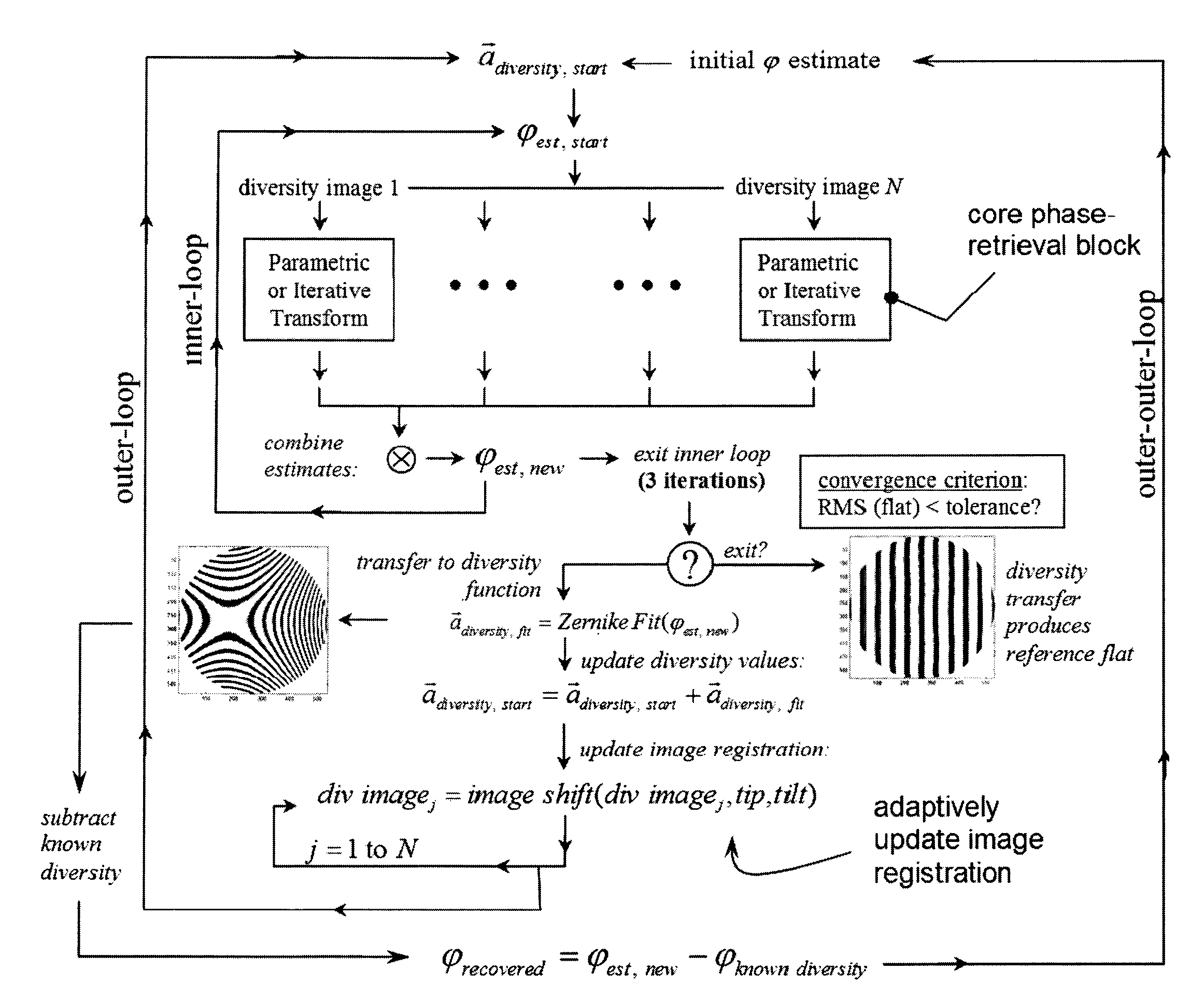
[0010]In one embodiment, the invention provides a method of recovering unknown aberrations in an optical system, comprising collecting intensity data produced by the optical system, generating an initial estimate of a phase of the optical system, iteratively performing a phase retrieval on the intensity data to generate a phase estimate using an initial diversity function corresponding to the intensity data, generating a phase map from the phase retrieval phase estimate, decomposing the phase map to generate a decomposition vector, generating an updated diversity function by combining the initial diversity function with the decomposition vector, generating an updated estimate of the phase...


PUM


Abstract

A method of recovering unknown aberrations in an optical system includes collecting intensity data produced by the optical system, generating an initial estimate of a phase of the optical system, iteratively performing a phase retrieval on the intensity data to generate a phase estimate using an initial diversity function corresponding to the intensity data, generating a phase map from the phase retrieval phase estimate, decomposing the phase map to generate a decomposition vector, generating an updated diversity function by combining the initial diversity function with the decomposition vector, generating an updated estimate of the phase of the optical system by removing the initial diversity function from the phase map. The method may further include repeating the process beginning with iteratively performing a phase retrieval on the intensity data using the updated estimate of the phase of the optical system in place of the initial estimate of the phase of the optical system, and using the updated diversity function in place of the initial diversity function, until a predetermined convergence is achieved.

Description

CROSS REFERENCE TO RELATED APPLICATIONS[0001]The benefit of priority is claimed under 35 U.S.C. 119(e) of commonly assigned U.S. Provisional Patent Application No. 60 / 713,616, filed Aug. 31, 2005, entitled “Wavefront Sensing Devices and Methods,” which is incorporated by reference herein in its entirety.STATEMENT OF GOVERNMENT INTEREST[0002]The invention described herein was made by an employee of the United States Government and may be manufactured and used by or for the Government of the United States of America for governmental purposes without the payment of any royalties thereon or therefor.FIELD OF THE INVENTION[0003]The present invention relates generally to optical systems and, in particular, to the recovery of aberrations in optical systems.BACKGROUND OF THE INVENTION[0004]Phase retrieval is an image-based wavefront sensing method that utilizes point-source images or other known objects to recover optical phase information.[0005]Conventional image-based phase retrieval tech...

Claims


Application Information

Patent Timeline
Patent Type & Authority Patents(United States)
IPC IPC(8): H01L27/00
CPCG01M11/005G03F7/706G03F7/705
Inventor DEAN, BRUCE H.
Owner NASA
Learn More