Diagnostic method and control apparatus for gas sensor

a control apparatus and sensor technology, applied in electrical control, fire alarms, instruments, etc., can solve the problems of inability to diagnose accurately, affecting noise, and affecting the output of the gas sensor,

Inactive Publication Date: 2009-12-22
NGK SPARK PLUG CO LTD
View PDF23 Cites 3 Cited by
  • Summary
  • Abstract
  • Description
  • Claims
  • Application Information

AI Technical Summary

Benefits of technology

[0006]Therefore, it is an object of the present invention to provide gas sensor diagnostic or control method and / or apparatus suitable for detecting an improper condition of a gas sensor accurately.

Problems solved by technology

However, the sensor output of the gas sensor may have a plurality of peaks in its waveform, and may be affected by noise.
Therefore, the diagnosis tends to be inaccurate and unstable when the diagnosis is configured to compare a sensor output value directly with a reference value, and to judge that there occurs a malfunction if a single sensor output value becomes greater than a reference value.

Method used


Image

  • Diagnostic method and control apparatus for gas sensor
  • Diagnostic method and control apparatus for gas sensor
  • Diagnostic method and control apparatus for gas sensor

Examples


first embodiment

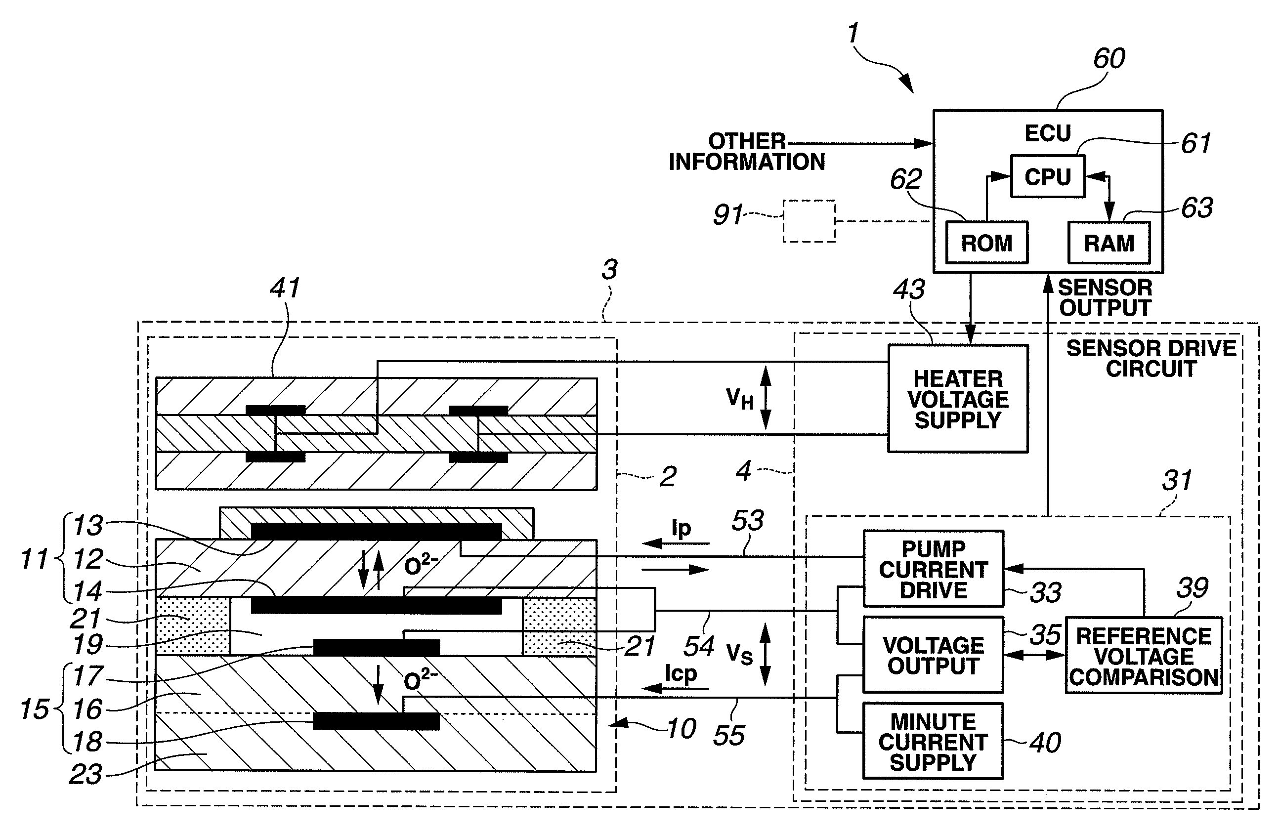
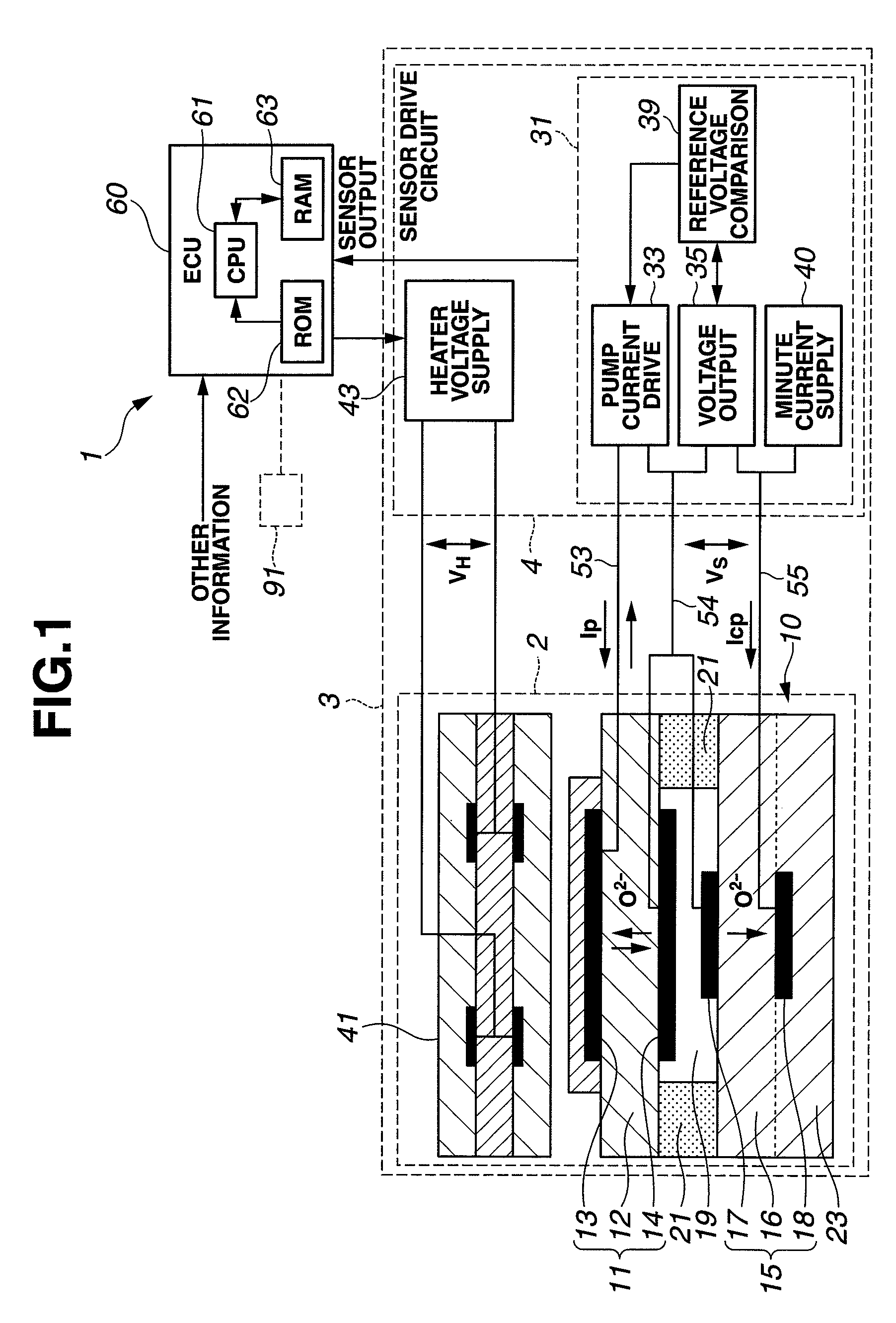
[0020]FIGS. 1˜6 show a gas sensor diagnosis or diagnostic method for determining whether a gas sensor is in an abnormal state or not, and a gas sensor system, according to the present invention. As shown in FIG. 1, the gas sensor system includes a gas sensor unit 3 and a gas sensor control device or controller 1. In the example shown in FIG. 1, gas sensor unit 3 employs a wide-range (or full-range) air-fuel ratio sensing element 10 (hereinafter referred simply as sensing element 10) capable of sensing the oxygen concentration in a wide (or full) range of the air-fuel ratio from the rich region to the lean region across the theoretical air-fuel ratio. In this example, the gas sensor system is arranged to sense the concentration of oxygen contained in exhaust gases of an internal combustion engine for a vehicle, by using the sensor output of gas sensor unit 3, and to use, or enable the use of, the sensed oxygen concentration for the control (such as feedback control) of the air-fuel r...

second embodiment

[0072]The diagnosis of S30 is arranged as shown in FIGS. 7 and 8 in the case of the In this example, CPU 61 shown in FIG. 1 performs the process of FIGS. 7 and 8 according a program stored in ROM 62, as well as other programs performed by ECU 60. The diagnostic process shown in FIGS. 8 and 9 includes steps substantially identical to steps shown in FIG. 6. Therefore, these steps are given the same step numbers and their detailed explanation is omitted or simplified.

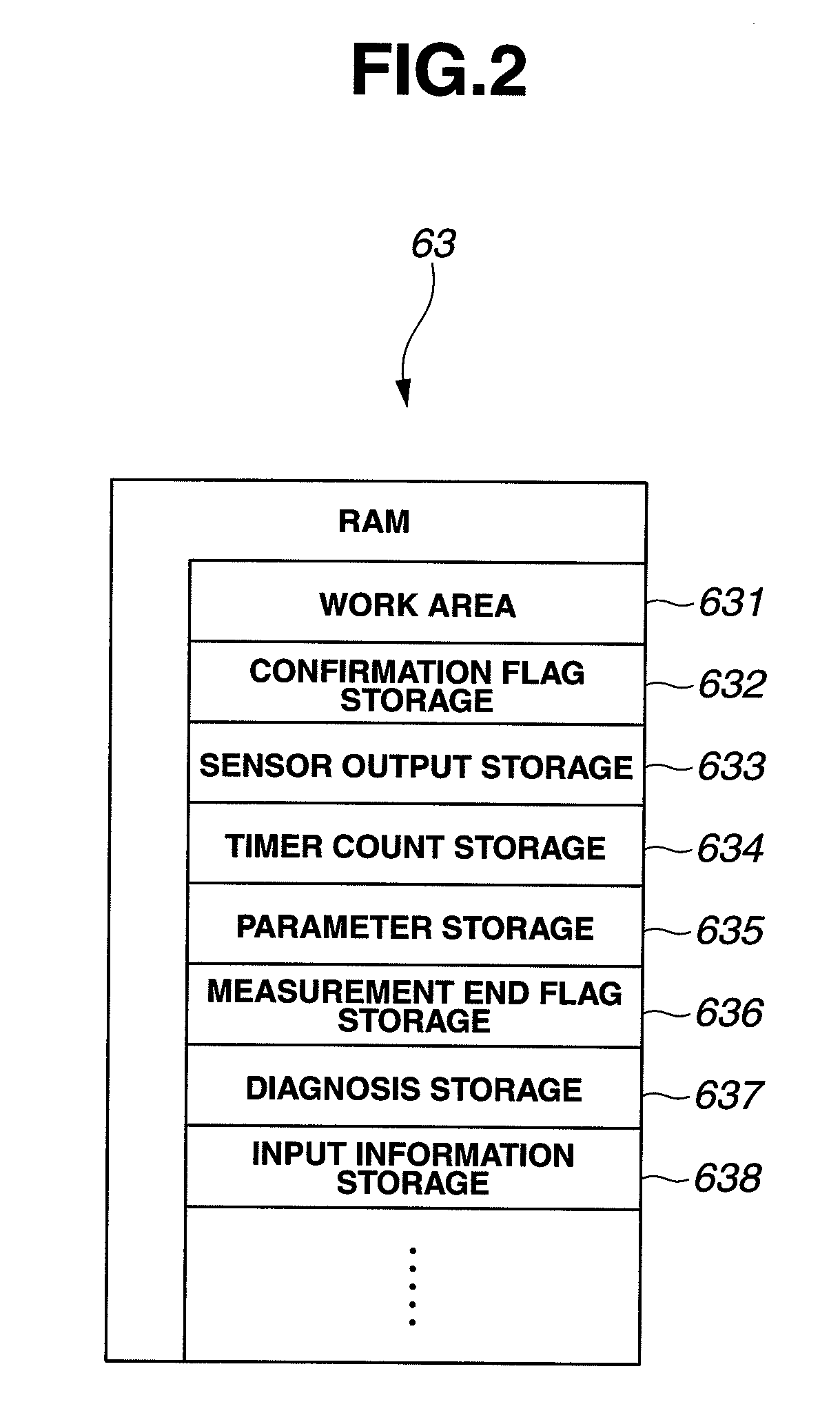
[0073]Steps S305, S310 and S315 in FIG. 7 are substantially identical to S305, S310 and S315 of FIG. 6. When at least one of the conditions of S305, S310 and S315 is not satisfied, CPU 61 proceeds from S305, S310 or S315, to a step S451. At S451, CPU 61 resets the primary diagnostic parameters Vmax, Nm, Nn, Na and Nb to zero, and stores the results in parameter storage area 635 of RAM 63 like step S450 of FIG. 6. At S451, moreover, CPU 61 further resets the secondary diagnostic parameters including the maximum accumulatio...


PUM

PropertyMeasurementUnit
voltageaaaaaaaaaa
temperatureaaaaaaaaaa
electromotive forceaaaaaaaaaa

Abstract

A gas sensor diagnostic method (or apparatus) is arranged to periodically obtain sensor output values of a gas sensor such as an oxygen sensor for an internal combustion engine, and to determine local extreme values from the sensor output values obtained during a period of interruption of fuel supply to the engine. Moreover, the local extreme values are compared with a first predetermined threshold level. When the number of the local extreme values reaches a predetermined first number, a diagnosis is performed to determine whether the gas sensor is in an improper condition or not, in accordance with results of the comparison of the local extreme values with the first threshold level.

Description

BACKGROUND OF THE INVENTION[0001]The present invention relates to gas sensor diagnosing method for examining whether a gas sensor disposed in an exhaust passage of an internal combustion engine is in an improper condition or not, and / or gas sensor control or diagnostic apparatus for such a gas sensor.[0002]A three-way catalyst is widely used in internal combustion engines for motor vehicles and other applications, to purify CO, HC and NOx contained in exhaust gas mixture. Furthermore, in order to improve the efficiency of the purification, there is provided a feedback air-fuel ratio control system including a gas sensor disposed in the exhaust passage of the engine, for sensing the oxygen concentration in the exhaust gases, and a controller for controlling the mixture ratio or air-fuel ratio toward the theoretical air-fuel ratio by regulating a fuel supply quantity, such as a fuel injection quantity, to the engine in accordance with the sensed oxygen concentration. Recently, the fee...

Claims


Application Information

Patent Timeline
Patent Type & Authority Patents(United States)
IPC IPC(8): G06F19/00G01N27/404
CPCF02D41/1438F02D41/123F02D41/1454F02D41/1495G01N27/4175
Inventor FUKAGAI, REINAIEDA, NORIKAZUTANAKA, MASAHIROINAGAKI, HIROSHIHIRATA, MASAKISUZUKI, TAKAHIRO
Owner NGK SPARK PLUG CO LTD
Why Eureka
Try Eureka