Vehicle seat assembly

a seat and assembly technology, applied in the field of seat assembly, can solve the problems of increasing manufacturing costs, increasing weight, and inability to provide an appropriate comfortable position for the seat assembly, and achieve the effect of preventing hip sliding and simple configuration

Active Publication Date: 2009-12-29
NHK SPRING CO LTD
View PDF29 Cites 50 Cited by
  • Summary
  • Abstract
  • Description
  • Claims
  • Application Information

AI Technical Summary

Benefits of technology

[0010]A vehicle seat assembly according to an aspect of the present invention comprises a seat back, a seat cushion coupled to the seat back, and a seat cushion angle adjustment mechanism for adjusting a seat cushion angle of the seat cushion. The seat cushion angle adjustment mechanism comprises a seat cushion frame, a pivotal coupling member for pivotably coupling the seat cushion frame to a slider of a seat rail, a guided member coupled to the seat cushion frame and movement of the guided member being guided at a position away from a coupled position of the pivotal coupling member and the slider, and a guide member for guiding movement of the guided member in a specific angular direction crossing with a sliding direction of the slider so as to change a seat cushion angle with sliding of the seat cushion. The seat cushion angle adjustment mechanism achieves adjustment of the angle of the seat cushion to effectively prevent the hip-sliding in a simple configuration.
[0011]Preferably, the guide member engages the guided member and has a long hole for guiding movement of the guided member, which achieves adjustment of the seat cushion angle with only simple components. Moreover, it is preferable that the slider slides substantially linearly on along the seat rail, and the guide member guides the guided member to move linearly toward the specific angular direction. This improves general versatility of the seat cushion angle adjustment mechanism.
[0012]Preferably, the guide member is formed integrally with a bracket to fix the seat rail to a vehicle body. This reduces the assembling man-hours and improves assembling accuracy as well.
[0013]Preferably, the seat back comprises an upper frame and a lower frame bendably coupled to the upper frame; the upper frame has a slide mechanism for sliding in the up-down direction of the seat; and the lower frame is pivotably coupled to a seat back side end of the seat cushion frame. According to this configuration, the seat cushion angle changes, the lower seat back moves forward, and the upper seat back moves downward in parallel as the seat cushion slides. This achieves a comfortable position for the occupant by a reclining angle preventing the hip-sliding and a folding angle for supporting the upper body of the occupant.
[0014]Preferably, couplers of a pair of the pivotal coupling members to the seat cushion frame are disposed to point to either one of the right and left directions of the seat on the right and left seat rails; and a pair of the guide members are disposed on the same side of either one of the right and left directions of the seat on the right and left seat rails. This is to improve work efficiency because the seat cushion angle adjustment mechanism can be assembled from one side.
[0015]The present invention achieves a seat cushion angle adjustment mechanism in a simple configuration which provides a comfortable relaxing position for an occupant, preventing the hip-sliding.

Problems solved by technology

If the seat cushion slides forward in parallel as in the seat assembly in the Related Art Reference, a phenomenon so-called hip-sliding that the occupant's hip slides forward as his or her upper body leans backward is provoked so that the seat assembly may not be able to provide an appropriate comfortable position.
However, special shaped parts such as the curved seat rail are required so that the manufacturing cost increases.
In case that an individual device is used, increase of the number of components will cause increase in the weight in addition to increase of the manufacturing cost as a matter of course.
The increase in the weight may cause an undesired influence to the fuel consumption for the vehicle with the seat assembly mounted thereon.
Moreover, the space in the vehicle is limited so that a configuration is required to be fitted in a smallest space as possible.

Method used


Image

  • Vehicle seat assembly
  • Vehicle seat assembly
  • Vehicle seat assembly

Examples


Embodiment Construction

[0028]Hereinafter, a preferred embodiment to which the present invention is applicable will be described. For clearness of explanation, the following description and the accompanying drawings contain omissions and simplifications as appropriate. Throughout the drawings, the like components are denoted by like reference numerals, and their repetitive description is omitted if not necessary.

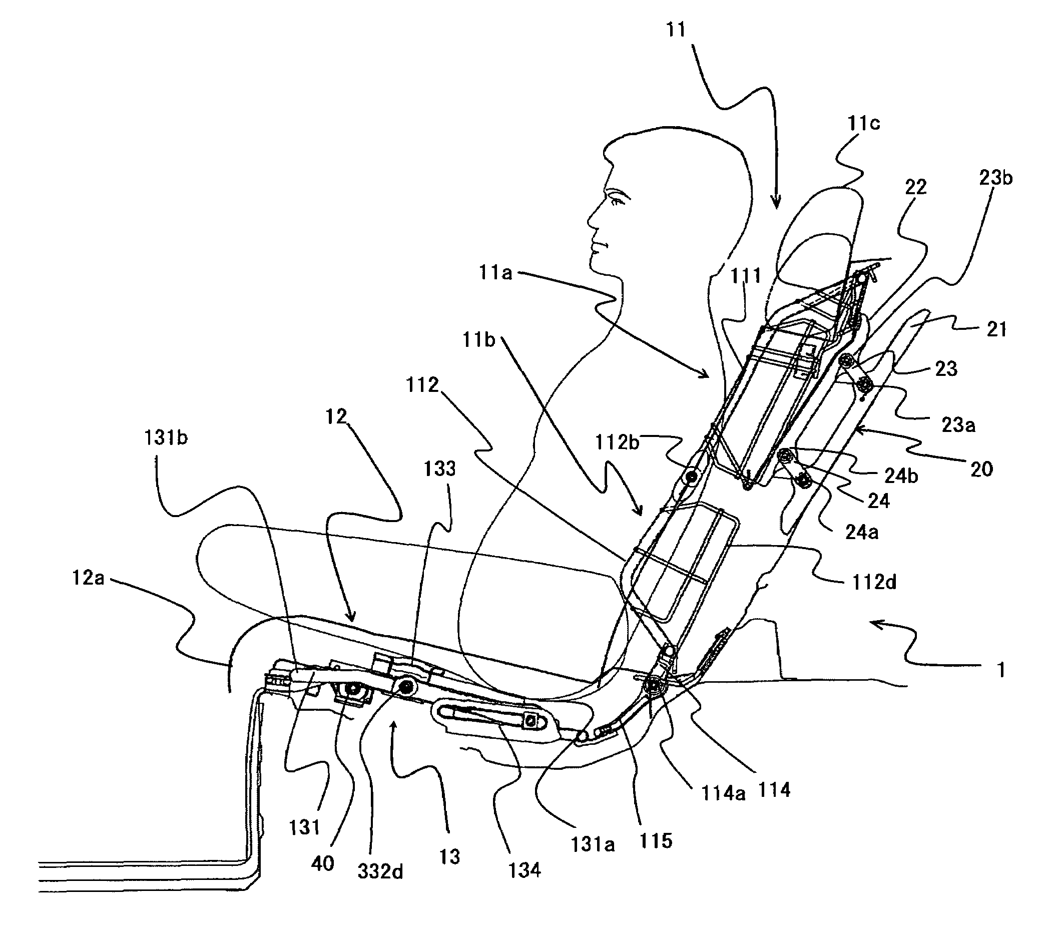
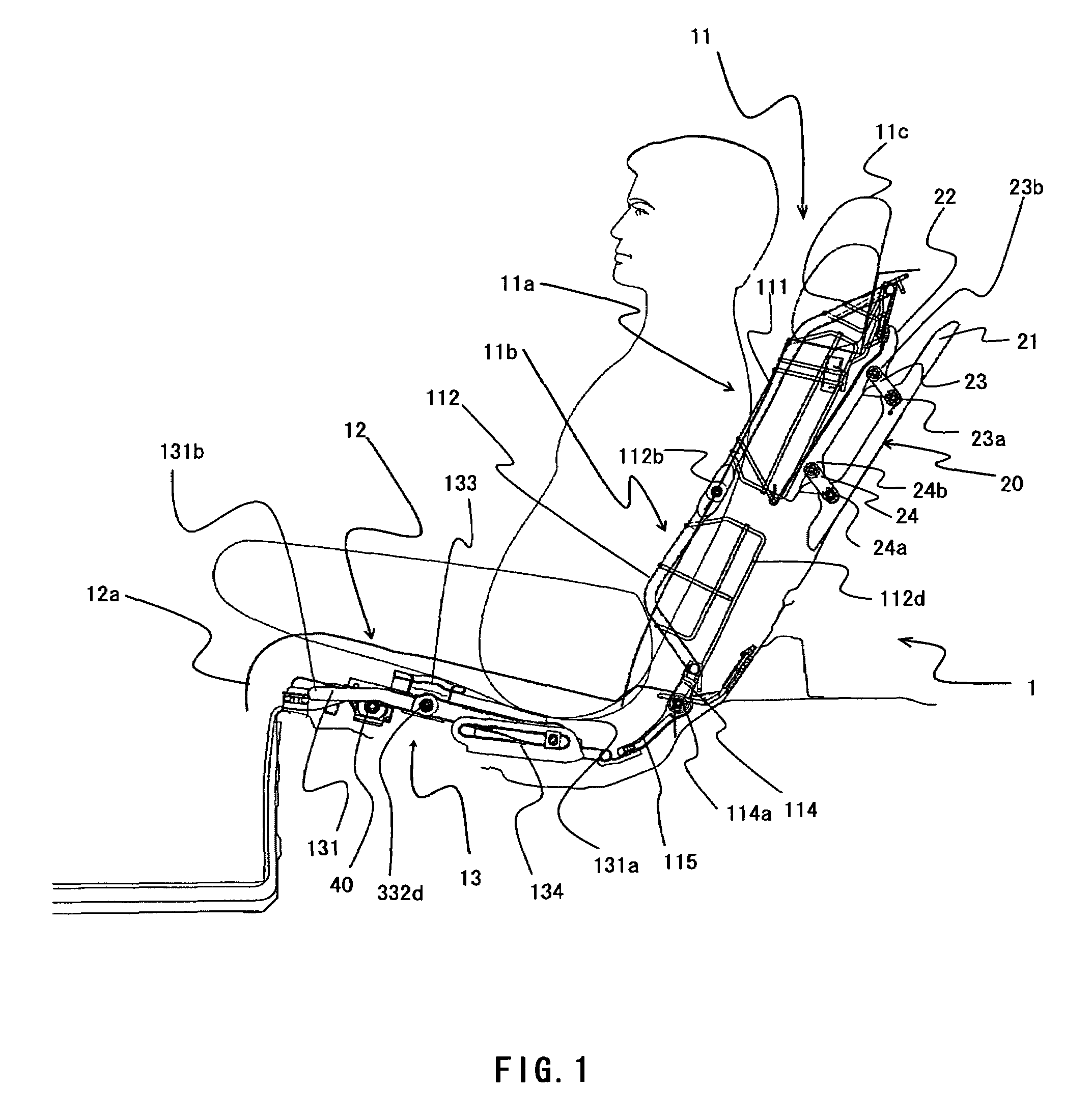
[0029]FIG. 1 schematically illustrates a partial configuration of a vehicle seat assembly 1 according to the present embodiment. The vehicle seat assembly 1 comprises a seat back 11 which is a back rest for an occupant to lean his or her back against it in his or her sitting position and a seat cushion 12 having a seat surface on which the occupant sits. The vehicle seat assembly 1 according to the present embodiment further comprises a seat cushion angle adjustment mechanism 13 for adjusting the seat cushion angle of the seat cushion 12 in accordance with the reclining movement of the seat. The ve...


PUM


Abstract

Disclosed is a vehicle seat assembly having a feature in a seat cushion angle adjustment mechanism of a seat cushion in a simple configuration. A vehicle seat assembly according to an embodiment of the present invention comprises a seat back, a seat cushion coupled to the seat back, and a seat cushion angle adjustment mechanism for adjusting the seat angle of the seat cushion. The seat cushion angle adjustment mechanism comprises a seat cushion frame, a pivotal coupling member to pivotably couple the seat cushion frame to a slider of the seat rail, a guided part provided at a position away from a coupled position of the seat cushion frame to the pivotal coupling member, and a guide member having a guide groove which engages the guided part and guides the movement of the guided part and disposed with an angle between the guide groove and the slide surface of the seat rail set to a specific angle α.

Description

[0001]This application claims priority from Japanese Patent Application No. 2007-008955 filed Jan. 18, 2007, which is incorporated herein by reference in its entirety.BACKGROUND OF THE INVENTION[0002]1. Field of the Invention[0003]The present invention relates to a vehicle seat assembly and more particularly to a vehicle seat assembly in which a seat cushion angle of a seat cushion is adjustable.[0004]2. Description of the Related Art[0005]Seat assemblies with reclining mechanisms to be used for automotive rear seats or the like have been known in the art. Such a seat assembly comprises a seat cushion having a seat surface on which an occupant sits and a seat back for supporting the occupant's back. In a typical seat assembly with a reclining mechanism, the seat cushion slides forward by the occupant's operation and the seat back interconnected to the seat cushion is drawn and moved by the seat cushion to define a reclining angle (for example, refer to Japanese Unexamined Utility-Mo...

Claims


Application Information

Patent Timeline
Patent Type & Authority Patents(United States)
IPC IPC(8): B60N2/12B60N2/00B60N2/02
CPCB60N2/1821B60N2/2222B60N2/2209B60N2/1839
Inventor OKANO, RITSUROHAGIWARA, SHINSUKEAOKI, JUN
Owner NHK SPRING CO LTD
Why Eureka
Try Eureka