Technique for sharing a physical port among a plurality of virtual bridges on a switch in a computer network

a virtual bridge and switch technology, applied in the field of computer networks, can solve the problems of high undesirable loops, circuitous paths or loops within the network, and the proliferation of data frames along loops

Inactive Publication Date: 2009-12-29
CISCO TECH INC
View PDF29 Cites 14 Cited by
  • Summary
  • Abstract
  • Description
  • Claims
  • Application Information

AI Technical Summary

Benefits of technology

[0031]Advantageously, the novel technique shares a physical port among a plurality of virtual bridges on a switch in a computer network. By configuring the virtual interfaces on the virtual bridges, the novel technique allows multiple virtual bridges to utilize a single physical port, particularly for use with the MST Protocol. In particular, the novel technique may be used with standard 802.1Q network configurations (i.e., non-proprietary configurations) because of the emulation of a “shared segment” by the novel shared trunk. Also, the novel technique is scalable to large computer networks, as the replication (e.g., software) may be necessary only for control messages, while data traffic may remain switched conventionally (e.g., hardware) over the physical port.

Problems solved by technology

The existence of redundant links, however, may cause the formation of circuitous paths or “loops” within the network.
Loops are highly undesirable because data frames may traverse the loops indefinitely.
Furthermore, some devices, such as bridges or switches, replicate frames whose destination is not known resulting in a proliferation of data frames along loops.
The resulting traffic can overwhelm the network.
The creation of large numbers of broadcast domains, however, may pose problems for the operation of the Multiple Spanning Tree Protocol, described below.
Because of this explicit mapping, MST Protocols must maintain a knowledge of the existence of all the configured VLANs (e.g., up to 4K), and it becomes relatively complex to support more and more VLANs in this manner (e.g., greater than 4K).
Specifically, this limitation currently prevents a switch from mixing VLANs (and bridge domains) belonging to different virtual bridges on the same port.

Method used


Image

  • Technique for sharing a physical port among a plurality of virtual bridges on a switch in a computer network
  • Technique for sharing a physical port among a plurality of virtual bridges on a switch in a computer network
  • Technique for sharing a physical port among a plurality of virtual bridges on a switch in a computer network

Examples


Embodiment Construction

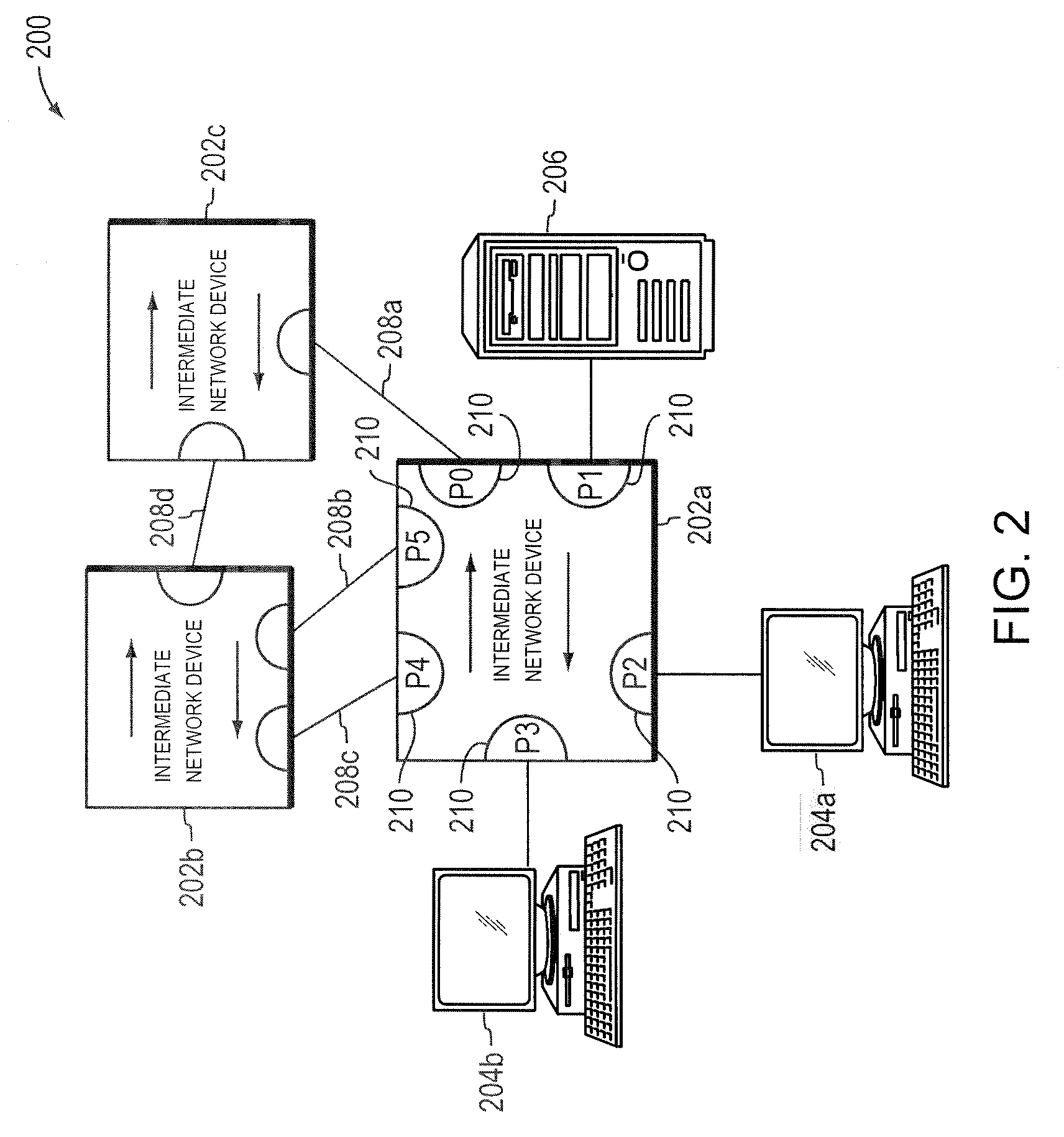
[0038]FIG. 2 is a highly schematic block diagram of an illustrative computer network 200 in which the present invention may be advantageously employed. Network 200 includes a plurality of interconnected intermediate network devices 202a-c. Devices 202a-c are preferably switches / bridges. In the illustrative embodiment, switches 202a-c conform to IEEE Std. 802.1D-2004 and IEEE Std. 802.1Q-2005, which are hereby incorporated by reference in their entireties. Attached to the switches 202a-c are network entities, such as local area networks (LANs) and / or end stations. In particular, workstations 204a-b and server 206 are directly attached to bridge 202a. The switches 202a-c, moreover, are interconnected with each other by a plurality of links 208a-d, which may be shared media / segments or point-to-point links / segments.

[0039]Each switch 202 has a plurality of ports 210 for receiving and forwarding messages across the network 200. The ports of each switch 202, moreover, may be identified, e...


PUM


Abstract

A technique shares a port (e.g., a physical port) among a plurality of virtual bridges on a switch in a computer network. According to the novel technique, two or more virtual bridges are established on the switch, and are each assigned respective sets of Virtual Local Area Networks (VLANs). Each virtual bridge has a virtual interface corresponding to the physical port (a “shared trunk”), the virtual bridges regarding the virtual interfaces as though they were physical ports. Control messages transmitted by the virtual bridges on the virtual interfaces are sent over the physical port and to each other virtual interface of the port (the shared trunk), such as, e.g., by a virtual hub of the shared trunk. Also, control messages received on the physical port are sent over each virtual interface to each virtual bridge (e.g., by the virtual hub).

Description

BACKGROUND OF THE INVENTION[0001]1. Field of the Invention[0002]The present invention relates to computer networks and more particularly to sharing a physical port among a plurality of virtual bridges on a switch in a computer network.[0003]2. Background Information[0004]Many organizations, including businesses, governments and educational institutions, utilize computer networks so that employees and others may share and exchange information and / or resources. A computer network typically comprises a plurality of entities interconnected by means of one or more communications media. An entity may consist of any device, such as a computer, that “sources” (i.e., transmits) or “sinks” (i.e., receives) data frames over the communications media. A common type of computer network is a local area network (“LAN”) which typically refers to a privately owned network within a single building or campus. LANs typically employ a data communication protocol (LAN standard), such as Ethernet, or a wir...

Claims


Application Information

Patent Timeline
Patent Type & Authority Patents(United States)
IPC IPC(8): H04L12/28
CPCH04L12/462H04L49/70H04L49/354H04L12/4641
Inventor TALLET, FRANCOIS EDOUARDMEHTA, MUNISH
Owner CISCO TECH INC
Why Eureka
Try Eureka