System and method for data center optical connection

a data center and optical connection technology, applied in the field of data center optical connection system and method, can solve the problems of dictating at least a portion of implementation cost and limited to a 100 meter reach, and achieve the effect of simplifying cabling, simplifying connections, and reducing cost components

Active Publication Date: 2016-04-26
HEWLETT-PACKARD ENTERPRISE DEV LP
View PDF26 Cites 10 Cited by
  • Summary
  • Abstract
  • Description
  • Claims
  • Application Information

AI Technical Summary

Benefits of technology

[0017]The present disclosure provides a connectivity device that permits simplified connections for realizing complex networking topologies using lower cost components. The device can be optically passive, or can have an active aspect to control switching to realize additional topology related features. The device permits cabling to be simplified and permits reduced cost cabling to be used to make connections while providing implementations of complex networking topologies. The device assists in simplifying connectivity implementation, so that complex networking topologies can be realized faster and with greater reliability.
[0024]According to another aspect of the present disclosure, a fiber shuffle device is provided that can accommodate relatively small and relatively large network topologies with reduced complexity and simplified scale-out options. The fiber shuffle device can be implemented as a low cost 1 U device with a number of MTP connection receptacles. The MTP connection receptacles are designed to receive MTP cable plugs to implement cable connectivity with the fiber shuffle device. In the present description, MTP connection plugs and receptacles are referred to as “connectors” to simplify the discussion in the general case, and with the more specific terms used separately to designate the specific functions of the plug or receptacle. According to one aspect, sets of MTP connectors are organized that permit a smaller scale network topology to be deployed, using one set of MTP connectors for connections, for example, while reserving another set for scale-out deployments.
[0026]Multiple fiber shuffle devices can be used to implement complex network topologies, by degrees, including such topologies as single or multi-dimensional ring meshes, chordal rings, toroid meshes, flattened butterfly architectures and grid architectures. The arrangement of the fiber shuffle device permits the topologies to be implemented with a small number of switches or nodes, and scale-out to significantly larger networks with tens or hundreds of switches or nodes, without significantly increasing complexity or relative costs, since low cost optical fiber connectors can be used to connect switches or nodes, and the switches or nodes themselves need not have a high port count. In addition, the number of cables used to implement complex topologies can be reduced, even as the network is scaled-out.

Problems solved by technology

Typically, data center network implementation involves connectivity that uses optical technology, which tends to dictate at least a portion of implementation cost.
The above 850 nm 12 channel module tends to be the lowest cost solution but may be limited to a 100 meter reach.

Method used


Image

  • System and method for data center optical connection
  • System and method for data center optical connection
  • System and method for data center optical connection

Examples


example 1

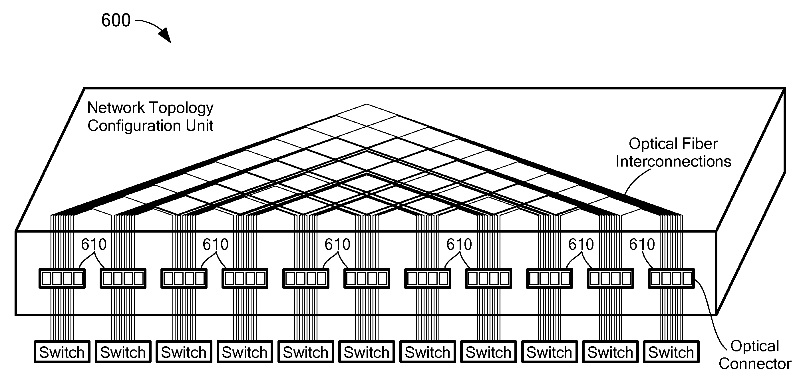
[0051]In accordance with an exemplary embodiment, NTCU 600 is used to replace 24 CWDM cables for a switch 1, and 48 CWDM cables for a switch 2, with 6 Silicon Photonic QSFP+ for switch 1 and 12 QSFP+ for switch 2. This eliminates a CWDM MUX / DMUX module, providing significant costs savings. Two 24 SM fiber MTP connectors are used to connect each of switch 1 and switch 2 to NTCU 600, and can be suitably labeled, such as “West / East.” The optical cost reduction can be on the order of from one quarter to one third of the implementation cost without NTCU 600.

[0052]The above example shows the cost benefits of using NTCU 600 on the basis of reducing cable runs used to implement the network connections. In addition, the network connections can scale with 3-D, 4-D mesh for very large data center, as the 4 km reach of the lower cost fiber can cover even the largest data center. Accordingly, as a data center scales-out, more expensive fiber options need not be deployed when NTCU 600 is used to ...

example 2

[0053]In accordance with the present example, two optical MTP cables are used for each switch to implement a CWDM ring solution in conjunction with the fiber shuffle device of the present disclosure. This number of optical MTP cables is twice that of a conventional ring implementation, where each switch is directly connected to a neighboring switch. However, the use of two MTP cables per switch is still manageable with regard to cost, and permits straightforward scale-out and simplified management of cabling and connectivity. For example, if it were desired to change the CWDM ring to another topology, such as a chordal ring, the connections for the new topology can be made with relative simplicity and ease at the fiber shuffle device of the present disclosure. Thus, the cables and connections can be changed at a single location, to produce a new network topology, without having to add cables, or change cable connections at the switches themselves.

[0054]While the above discussion ill...


PUM


Abstract

A connectivity device permits simplified connections for realizing complex networking topologies using lower cost components. The device can be optically passive, or can have an active aspect to control switching to realize additional topology related features. The device permits cabling to be simplified while reducing cost to permit implementations of complex networking topologies to be realized faster and with greater reliability. The device aids in scaling out a network implementation and can provide connectivity for an arbitrary number of nodes with efficient capacity usage.

Description

[0001]The present application claims benefit of U.S. Provisional Application No. 61 / 793,191, filed Mar. 15, 2013 and entitled “SYSTEM AND METHOD FOR DATA CENTER OPTICAL CONNECTION,” and also claims benefit of U.S. Provisional Application No. 61 / 845,587, filed Jul. 12, 2013, entitled “SYSTEM AND METHOD FOR DATA CENTER OPTICAL CONNECTION,” the entire disclosures of which are hereby incorporated herein by reference.STATEMENT REGARDING FEDERALLY SPONSORED RESEARCH OR DEVELOPMENT[0002](Not Applicable)BACKGROUND OF THE INVENTION[0003]Communication networks tend to be constructed according to various physical and / or logical topologies, which can often depend on the capabilities of the components of the communication network. For example, FIG. 1 shows a communication network 100 in a hierarchical topology previously used in enterprise and data center communication networks.[0004]Network 100 has a lower layer 110 comprised of servers 112, which are typically rack mounted or otherwise concent...

Claims


Application Information

Patent Timeline
Patent Type & Authority Patents(United States)
IPC IPC(8): H04L12/931H04L12/751H04L12/933H04L45/02
CPCH04L45/02H04L49/45H04L49/101H04L49/15H04Q2213/1301
Inventor LI, RUODINGSPOCK, DEREK E.BARRY, RICHARD A.
Owner HEWLETT-PACKARD ENTERPRISE DEV LP
Why Eureka
Try Eureka