Quick loading cutting head for a rotary trimmer

a rotary trimmer and cutting head technology, applied in metal working devices, agriculture tools and machines, agriculture, etc., can solve the problems of assembly parts that cannot be easily cleaned, non-smooth operation of the mowing device, etc., and achieve the effect of quick and easy loading and less fatiguing

Inactive Publication Date: 2010-01-05
KWIK PRODS
View PDF43 Cites 41 Cited by
  • Summary
  • Abstract
  • Description
  • Claims
  • Application Information

AI Technical Summary

Benefits of technology

[0010]An improved cutting head which may be more quickly and easily loaded with predetermined lengths of flail without requiring disassembly of the cutting head is provided. In one embodiment, a control mechanism is provided in the cutting head interacting between a follower member and a spool member so as to provide for one way rotational loading of the flails into the cutting head; in other words, to load the flails, the spool member is rotated continuously 360° in one direction only, e.g., clockwise. In another embodiment, a cutting head allows the flails to be loaded by a ratcheting-type operation, i.e., a back and forth rotational movement, which is less fatiguing and even more efficient in its loading operation.

Problems solved by technology

However, the specific construction of the tangs and the serpentinous cam slot in that device is designed to result in stress concentrations in the engaging members and, as a result, an abrupt and discontinuous operation of the feedout assembly occurs which results in potential wear of the assembly parts, as well as non-smooth operation of the mowing device.

Method used


Image

  • Quick loading cutting head for a rotary trimmer
  • Quick loading cutting head for a rotary trimmer
  • Quick loading cutting head for a rotary trimmer

Examples


Embodiment Construction

[0033]Preferred embodiments of the present disclosure will be described hereinbelow with reference to the accompanying drawings. In the following description, well-known functions or constructions are not described in detail to avoid obscuring the present disclosure in unnecessary detail.

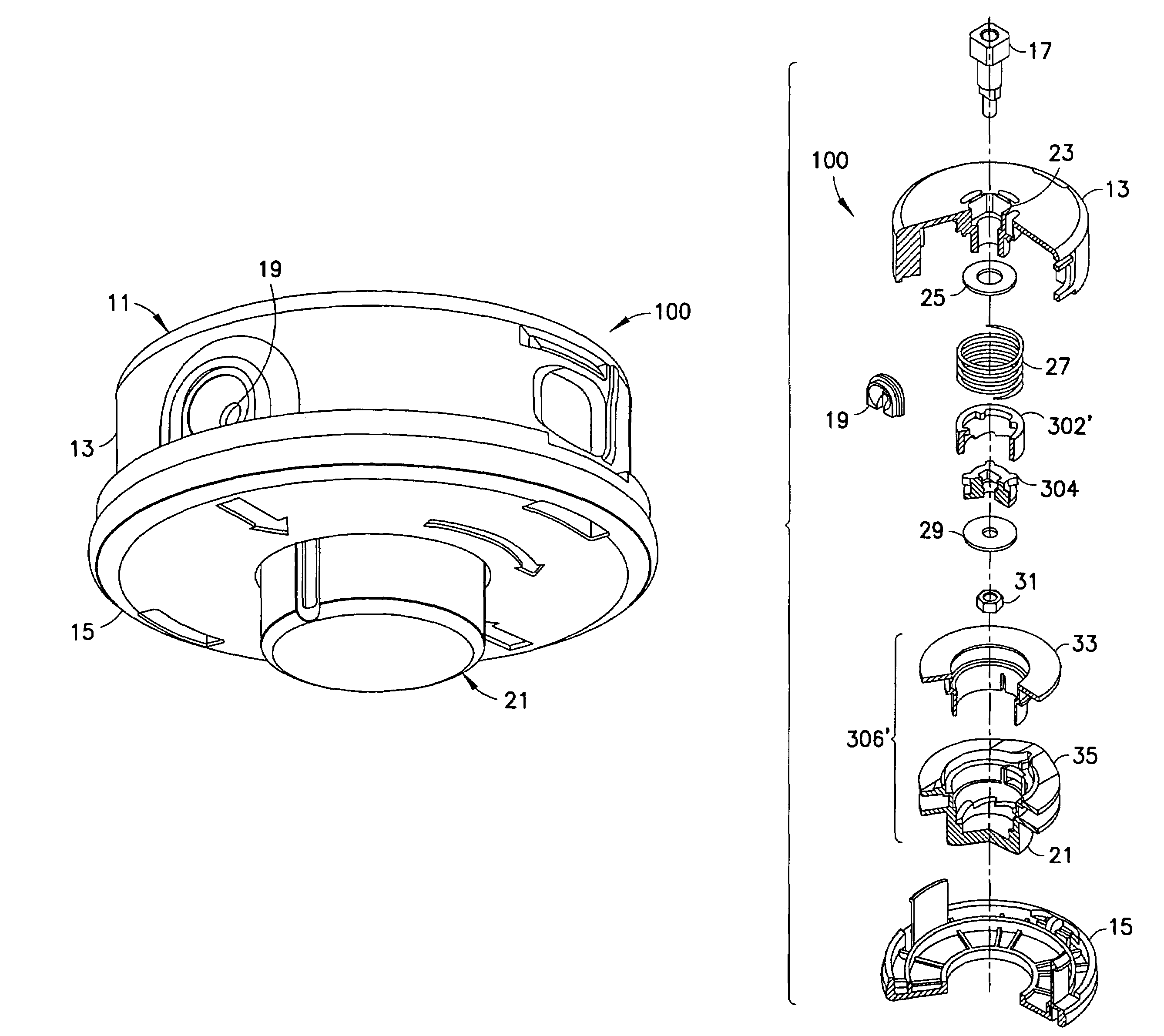
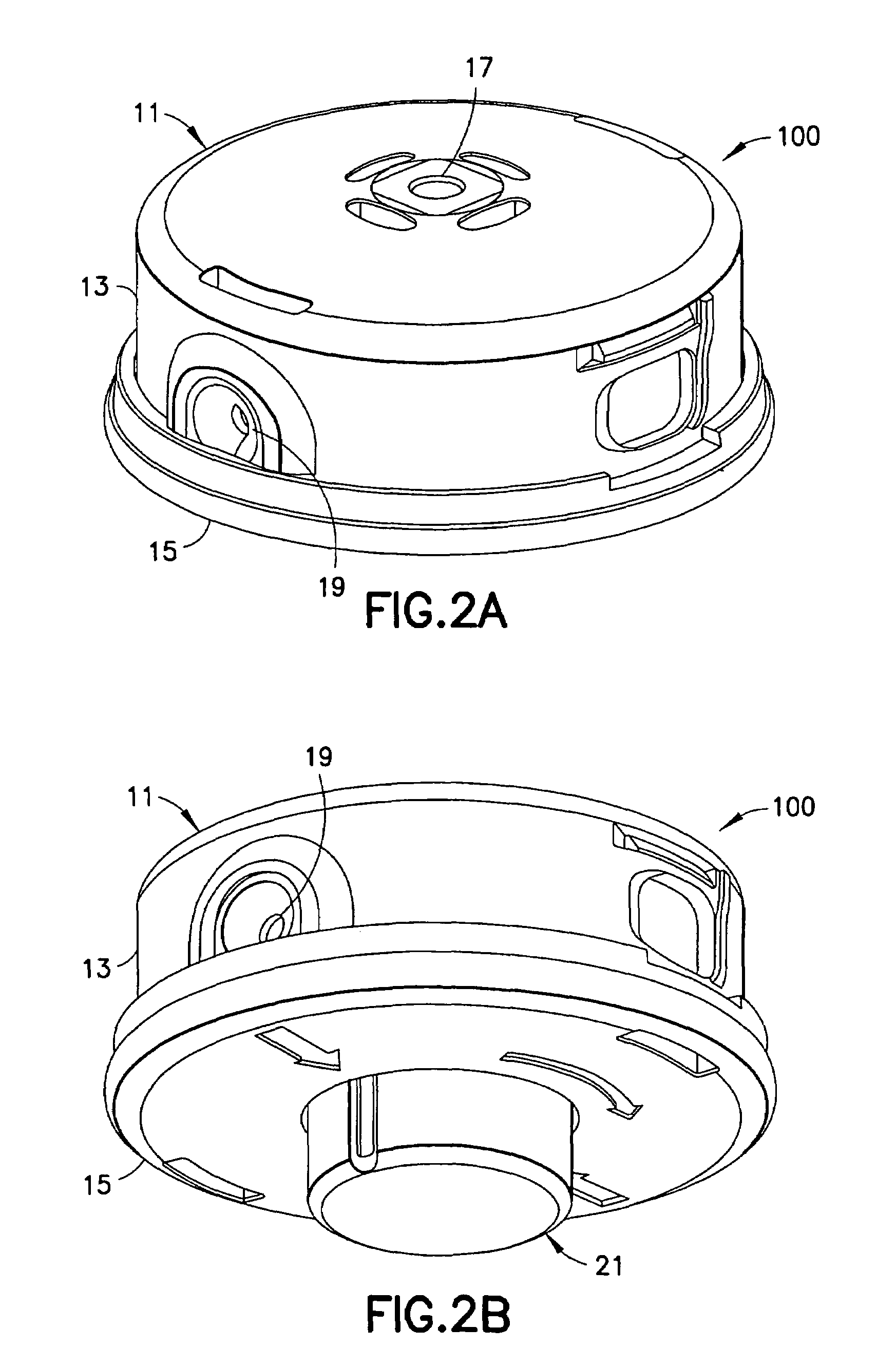
[0034]A cutting head for a rotary trimmer configured to facilitate loading of at least one cutting line, e.g., flail, is provided. Generally, a rotary trimmer includes a hollow handle with an attached drive means that is connected to a spinning housing, e.g., a cutting head. The housing has a spool member containing one or more coils of string used as filaments for cutting vegetation. A pair of orifices is oppositely positioned on the spool member for guiding the exposed filament to the proper cutting position.

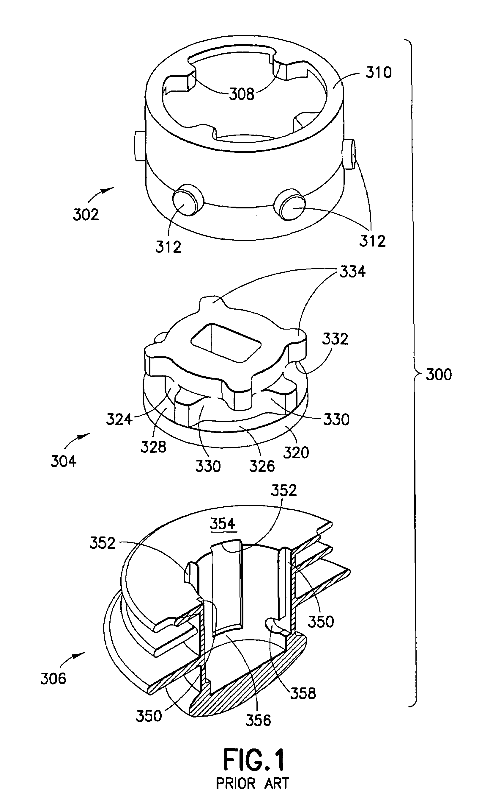
[0035]Turning to FIG. 1, the flail feed-out assembly of U.S. Pat. No. 6,735,874 is employed in the cutting head for a rotary trimmer of the present disclosure. The flail feed-out assembly 300 ...


PUM


Abstract

A cutting head for a rotary trimmer is provided. The cutting head of the present disclosure provides a control mechanism for loading a spool member of the cutting head quickly and efficiently without having to disassemble the cutting head. In one embodiment, a control mechanism is provided in the cutting head interacting between a follower member and a spool member so as to provide for one way rotational loading of flails, e.g., cutting line, into the cutting head; in other words, to load the flails, the spool member is rotated continuously 360° in one direction only, e.g., clockwise. In another embodiment, a cutting head allows the flails to be loaded by a ratcheting-type operation, i.e., a back and forth rotational movement, which is less fatiguing and even more efficient in its loading operation.

Description

PRIORITY[0001]This application claims priority to an application entitled “QUICK LOADING CUTTING HEAD FOR A ROTARY TRIMMER” filed in the United States Patent and Trademark Office on Dec. 8, 2005 and assigned Ser. No. 60 / 748,757, and an application entitled “RATCHET-TYPE, QUICK LOADING CUTTING HEAD FOR A ROTARY TRIMMER” filed in the United States Patent and Trademark Office on Dec. 29, 2005 and assigned Ser. No. 60 / 755,532, the contents of which are hereby incorporated by reference.BACKGROUND[0002]1. Field[0003]The present disclosure relates to cutting heads for rotary trimmers and, more specifically, it relates to an improved cutting head for rotary trimmers using continuous lengths of spooled monofilament strings as a means for cutting vegetation. The present disclosure represents an improvement over presently existing cutting head designs and allows for quick, smooth, ratchet-type efficient loading of the monofilament strings onto the spool of a cutting head.[0004]2. Description o...

Claims


Application Information

Patent Timeline
Patent Type & Authority Patents(United States)
IPC IPC(8): B26B7/00
CPCA01D34/4163
Inventor IACONA, FERNANDO R.
Owner KWIK PRODS
Why Eureka
Try Eureka