Filter manifold

a filter manifold and filter technology, applied in the field of filter manifolds, can solve the problems of difficult confirmation, time-consuming and labor-intensive manual dexterity, and the use of filter capsule life, and achieve the effect of quick and easy loading

Active Publication Date: 2016-12-27
PALL CORP
View PDF21 Cites 2 Cited by
  • Summary
  • Abstract
  • Description
  • Claims
  • Application Information

AI Technical Summary

Benefits of technology

[0005]In accordance the present invention, a filter manifold system is provided which permits a filter capsule to be quickly and easily loaded and which permits the user to open the manifold when the filter capsule is properly seated in the manifold, thus insuring a proper fluid-tight seal between the capsule and manifold. The filter manifold comprises a filter capsule for filtering a substance-laden stream, a housing, and a carriage assembly disposed in the housing.
[0010]The valve preferably comprises a wedge sleeve which moves between an upper open position and a lower closed position. The wedge sleeve has a first hole which slidably receives the pinch arms and a tapered wall which slidably engages the pinch arms in response to movement between the upper open position and the lower closed position. The tapered wall causes the pinch arms to move to the closed position so that the valve is closed when the wedge sleeve is in the lower closed position. The tapered wall in the wedge sleeve permits the pinch arms to move to the open position when the wedge sleeve is in the upper open position.

Problems solved by technology

Similarly, when the useful life of the filter capsule has expired because, for example, the filter medium is clogged with the undesirable substances removed from the stream, the filter capsule must be removed from the manifold by manually untwisting the filter capsule's fitting from the corresponding fitting.
Since manifolds may hold multiple filter capsules, installing and removing multiple capsules may be a time consuming and intricate, manually dexterous process.
It may be difficult to confirm when the filter capsule is properly seated in the manifold and insure a proper fluid-tight seal between the capsule and manifold.
Similarly, it may also be difficult to insure that the filter capsule is present and properly seated before the feed and extract fittings are opened to introduce the stream into the capsule.
This is particularly important for many fluids which are toxic or corrosive, and when handling the capsule filled with the fluid may be hazardous.

Method used


Image

  • Filter manifold
  • Filter manifold
  • Filter manifold

Examples


Embodiment Construction

[0029]It will be appreciated that this detailed description provides exemplary embodiments of the invention. Since other embodiments of the invention may differ in detail from the embodiments in this detailed description, the detailed description is intended to reference the particular embodiments being discussed at that point and is not intended to imply any limitation as to the scope of the invention more generally.

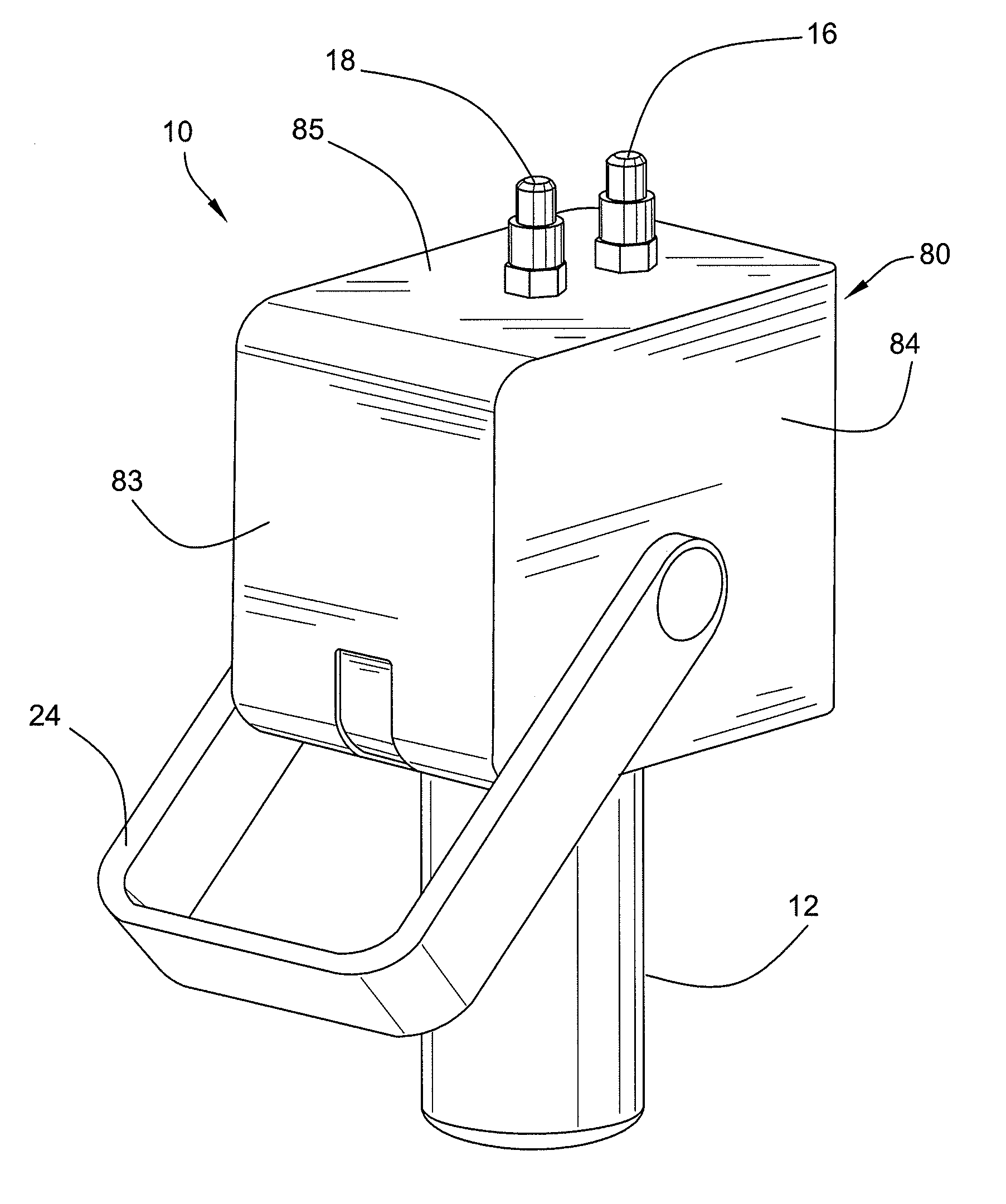
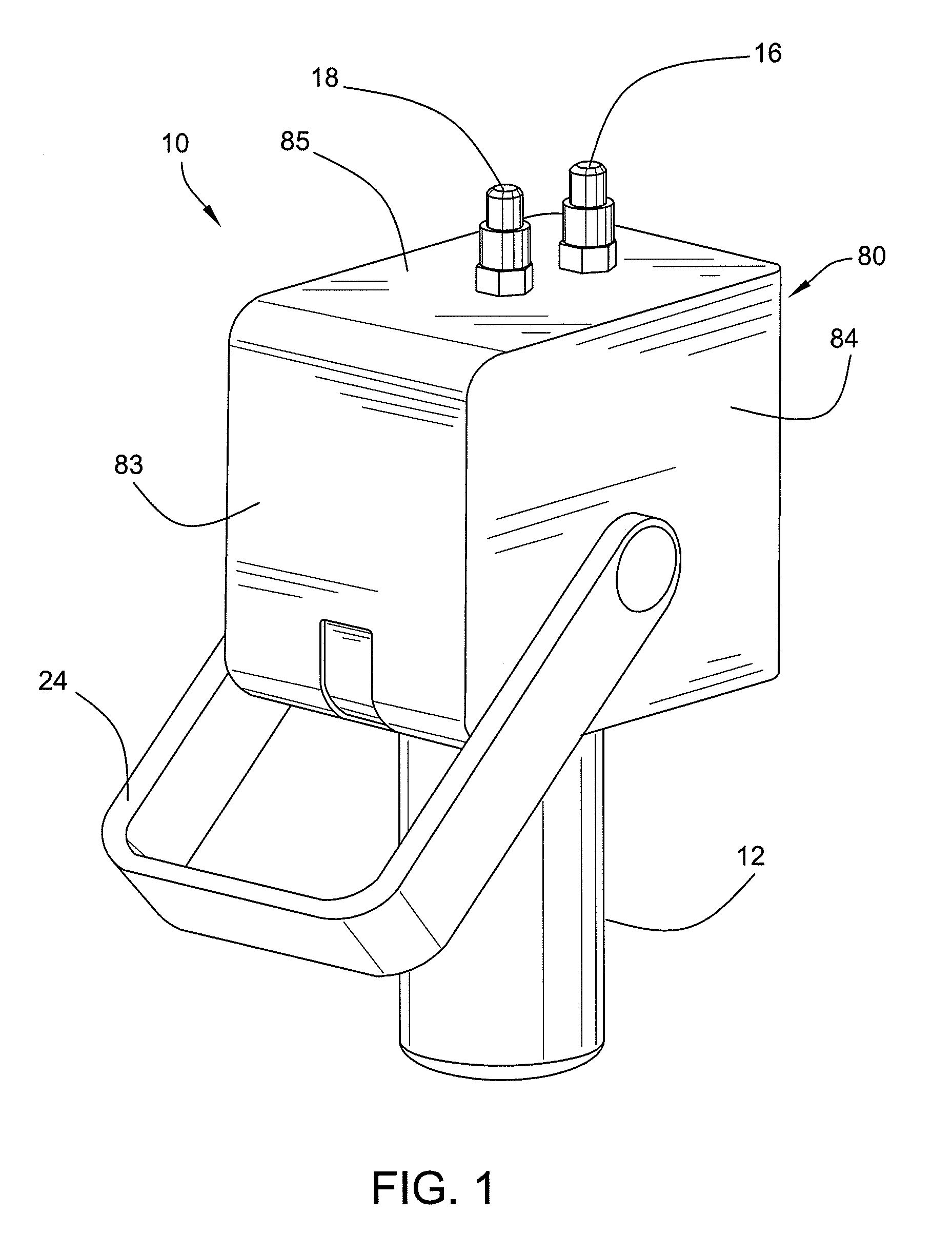
[0030]FIG. 1 illustrates a manifold 10 for receiving and holding a filter capsule 12, and then creating a fluid-tight seal with the filter capsule 12 so that a fluid or gas stream may be introduced into and extracted out of the filter capsule 12. During normal operation, the internal components of the manifold 10 are normally covered by an exterior housing 80, including front plate 83, two side plates 84, top plate 85 and rear plate 86. For ease of reference, the housing 80 has been removed in many of the drawings to facilitate illustration of the invention. The manifol...


PUM

PropertyMeasurementUnit
flexibleaaaaaaaaaa
rotationaaaaaaaaaa
corrosiveaaaaaaaaaa

Abstract

A filter manifold is provided for filtering particulates in fluid and gas streams. The filter manifold seals the inlet and outlet valves in a closed position until a filter capsule is loaded into a carriage assembly. The inlet and outlet valves are opened only when a filter capsule is properly loaded into the carriage assembly.

Description

TECHNICAL FIELD[0001]This invention relates to filter manifolds and, more particularly, to manifolds for holding cylindrical filter capsules.BACKGROUND[0002]Filter capsules have a cylindrical filter element for filtering undesirable substances from fluid and gas streams. The undesirable substances may include solid or colloidal particulates, gels, and gas bubbles. Filter capsules have at least inlet and outlet ports and a housing for directing the stream between the inlet and outlet ports. Filter capsules also have a filter medium disposed between the inlet and outlet ports, which filters the undesirable substances in the stream.[0003]A manifold may be used to introduce the fluid / gas stream to be filtered into the filter capsule and extract the clean stream from the filter capsule. The manifold may supply the substance-laden stream to the filter via the inlet port, and may extract the filtered stream, or filtrate, via the outlet port. The filter must be mounted in the manifold so th...

Claims


Application Information

Patent Timeline
Patent Type & Authority Patents(United States)
IPC IPC(8): B01D35/30B01D46/42
CPCB01D35/30B01D46/4227B01D2201/24B01D2201/303B01D2201/4023
Inventor GATICA, ANTHONY WILLIAMPALERMO, BRIAN ANTHONYFOOHEY, MARK WILLIAM
Owner PALL CORP
Why Eureka
Try Eureka