Boat support frame loading and unloading apparatus

a technology for supporting frames and boats, which is applied in the direction of waterborne vessels, transportation items, items transportation vehicles, etc., can solve the problems of boat users getting wet, difficulty in employing effective winch based retrieval systems, and slow winch based systems, whether they be manually cranked or driven by electric motors

Active Publication Date: 2017-03-16
BALEX MARINE DEV LTD
View PDF4 Cites 4 Cited by
  • Summary
  • Abstract
  • Description
  • Claims
  • Application Information

AI Technical Summary

Benefits of technology

[0093]However in a preferred embodiment a compression element may be formed by a hydraulic or pneumatic ram assembly. In such embodiments a ram chamber may be charged with pressurised gas or liquid to raise an associated roller assembly prior to th...

Problems solved by technology

Winch based retrieval systems are difficult for some users to employ effectively, while also requiring the boat and the trailer to be precisely aligned with the winch rope secured to a strong point at the bow of the boat.
Furthermore, the loading of boat trailers with winches will normally result in the boat user getting wet.
Winch based systems—whether they be manually cranked or driven by an electric motor—are also relatively slow.
Gearing systems are also employed with winches used to retrieve relatively heavy boats, allowing the winch to a load the boat but at the cost of significantly slower loading speeds.
This approach will expose the trailer frame and its associated components to water (and frequently saltwater) which can damage the trailer components.
Salt water exposure in particular is very common for boat trailers and has a highly corrosive effect on metal components.
This approach can drastically shorten the useful lifespan of the electric motor and will promote accelerated metallic corrosion of the drive system components.
Furthermore the active or working components of this loading system are difficult to access for repair and maintenance operations.
Although positioning the motor used in an accessible location, the powered roller loading system disclosed in this document causes problems when a variety of boats with different hull shapes and designs are to be loaded...

Method used


Image

  • Boat support frame loading and unloading apparatus
  • Boat support frame loading and unloading apparatus
  • Boat support frame loading and unloading apparatus

Examples


Embodiment Construction

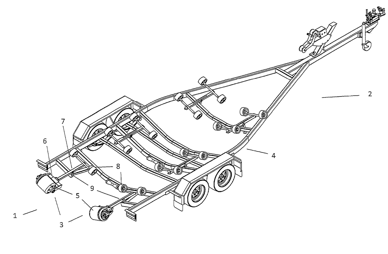
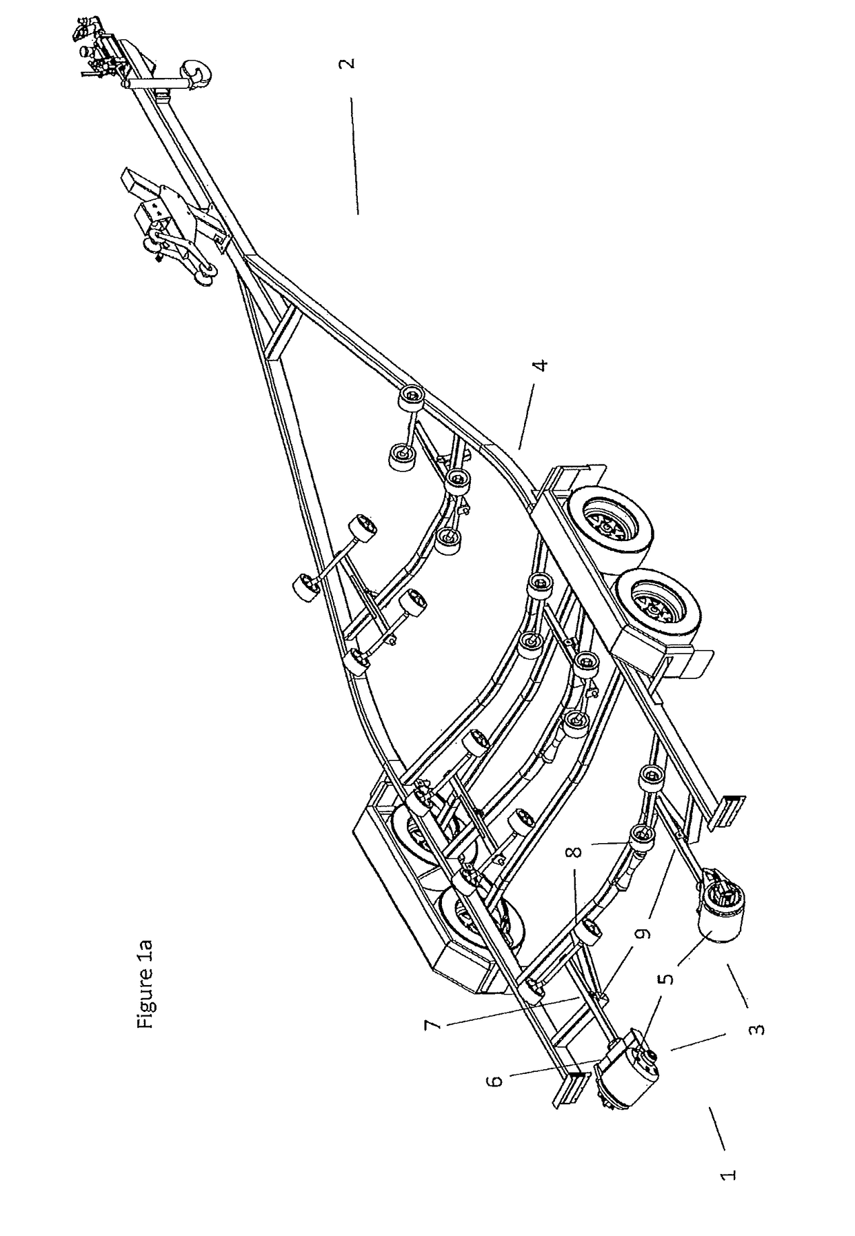
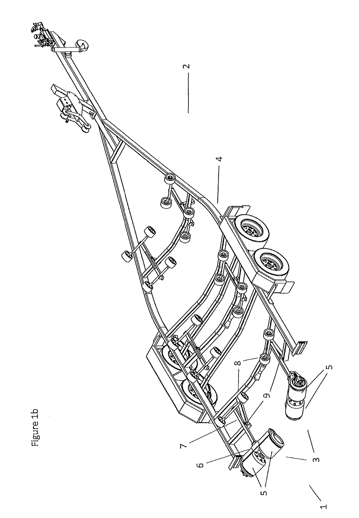
[0107]FIGS. 1a and 1b shows a perspective view of the invention used in two different embodiments to implement a loading and unloading apparatus 1 for a boat support frame formed from a road going trailer 2.

[0108]In this embodiment the invention is formed by a number of roller assemblies 3 positioned to the rear or loading end of the trailer. The roller assembles 3 are deployed with a symmetrical arrangement centered around the midline of the trailer frame 4.

[0109]In the embodiment shown with respect to FIG. 1a the roller assemblies 3 include a single roller element 5, while in the embodiment of FIG. 1b a pair of adjacent aligned roller elements 5 are provided.

[0110]Each roller assembly is enclosed by the ends of a mounting bracket 6 with each mounting bracket 6 connected to a carrier arm 7 to locate the roller assembly 3 in place on the trailer frame 4. The same carrier arm 7 is also used to deploy a passive roller 8 and provides the invention with a pivoting ‘wobble roller’ arrang...


PUM


Abstract

In one aspect the invention provides a boat support frame loading and unloading apparatus configured to draw a boat on to and off a boat support frame. This boat support frame has a loading end and a terminal end opposite to the loading end. The apparatus provided includes at least one roller assembly mounted to the support frame adjacent to the loading end of the support frame, said at least one roller assembly incorporating at least one roller element. The apparatus also includes at least one drive mechanism configured to rotate one or more roller elements to draw a boat onto and off the support frame through the loading end of the support frame. The roller assembly also includes a hull contact surface formed by a flexible belt which has a circumference greater than the circumference of the said at least one roller element incorporated into the roller assembly.

Description

TECHNICAL FIELD[0001]This invention relates to a boat support frame loading and unloading apparatus. In various embodiments the invention may be used to load and unload boats from mobile towed support frames, static support frame assemblies, or static support frames implemented in association with another form of vehicle.BACKGROUND ART[0002]Various applications require boats to be moved to and from a support frame and a body water.[0003]For example road going trailers are commonly used to transport boats overland and to store boats away from a body of water. Boat trailers allow a wide range of different sizes of water vessels to be deployed to and retrieved from bodies of water.[0004]Relatively simple boat trailers rely on the trailer being backed down a boat ramp and partially submerging the trailer. This then allows a boat to be pushed off the trailer with the assistance of a number of passive roller elements. When the boat is to be retrieved it must be accurately aligned with the...

Claims


Application Information

Patent Timeline
IPC IPC(8): B60P3/10B63C3/12
CPCB60P3/1066B60P3/1075B63C3/12
Inventor BACON, LEX NOELSYMES, PAUL ANTONYJONES, JONATHAN MARTINREES-JONES, BLYTHE GUYLEYBOURNE, DARRENPERCIVAL, ANDREW JAMESIVANOV, YURI NIKOLAEVICH
Owner BALEX MARINE DEV LTD
Why Eureka
Try Eureka