Eureka AIR delivers breakthrough ideas for toughest innovation challenges, trusted by R&D personnel around the world.

Tablet press

a tabletop and press technology, applied in the field of tabletop presses, can solve the problem of not being able to guarantee the tension necessary, and achieve the effect of not being disassembled

Active Publication Date: 2010-01-05
FETTE
View PDF2 Cites 5 Cited by
  • Summary
  • Abstract
  • Description
  • Claims
  • Application Information

AI Technical Summary

Benefits of technology

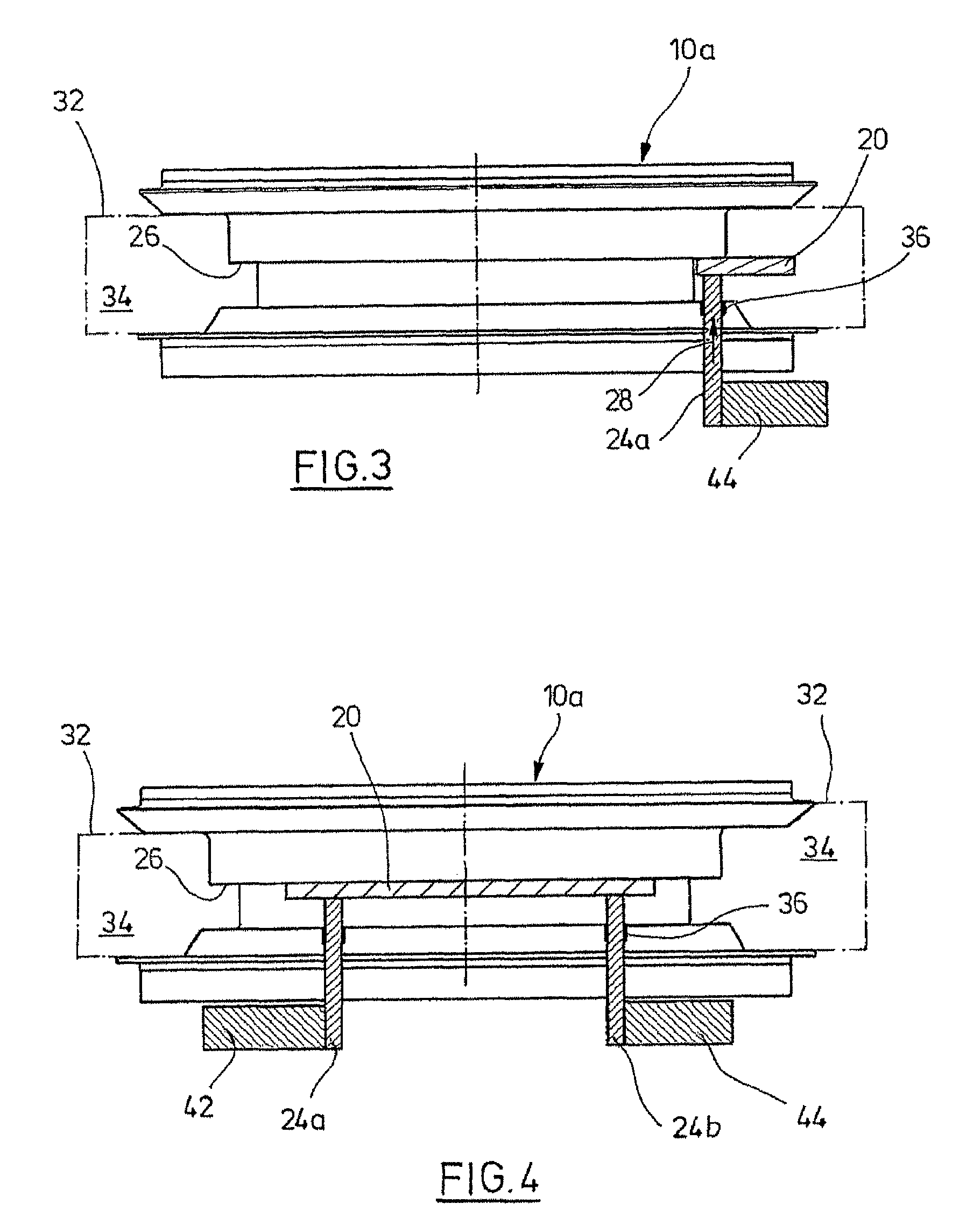
"The present invention provides a tablet press with a stand that has a drive device for the clamping elements. The drive device is adjustable in the stand and can be engaged with the lower end of the clamping element. The clamping elements are guided through a passage in the rotor and can be set into engagement with the bottom side of the assigned die segment. The drive device applies an axial pressing force on the clamping element to exert a preset clamping force on the assigned die segment. The stand must be adjusted by a corresponding rotation to align the drive element and the clamping element when the clamping element is to be actuated. The invention allows for automatic clamping, eliminating the need for an operator to apply a preset force on the clamping element. The rotor is surrounded by a stationary shell that co-operates sealingly with the rotor and forms a processing space, which allows for easy cleaning without disassembly of punches. Different embodiments are conceivable for how to bring the clamping elements into abutment with the segments of the die plate and how to select the number of drive devices."

Problems solved by technology

For this reason it might occur that the necessary tension is not guaranteed.

Method used


Image

  • Tablet press
  • Tablet press
  • Tablet press

Examples


Embodiment Construction

[0027]While this invention may be embodied in many different forms, there are described in detail herein a specific preferred embodiment of the invention. This description is an exemplification of the principles of the invention and is not intended to limit the invention to the particular embodiment illustrated

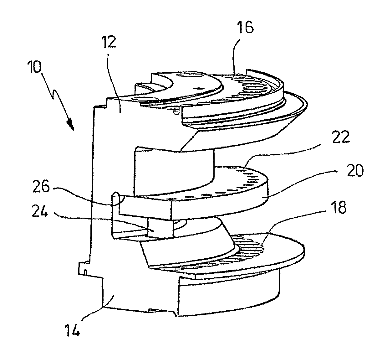
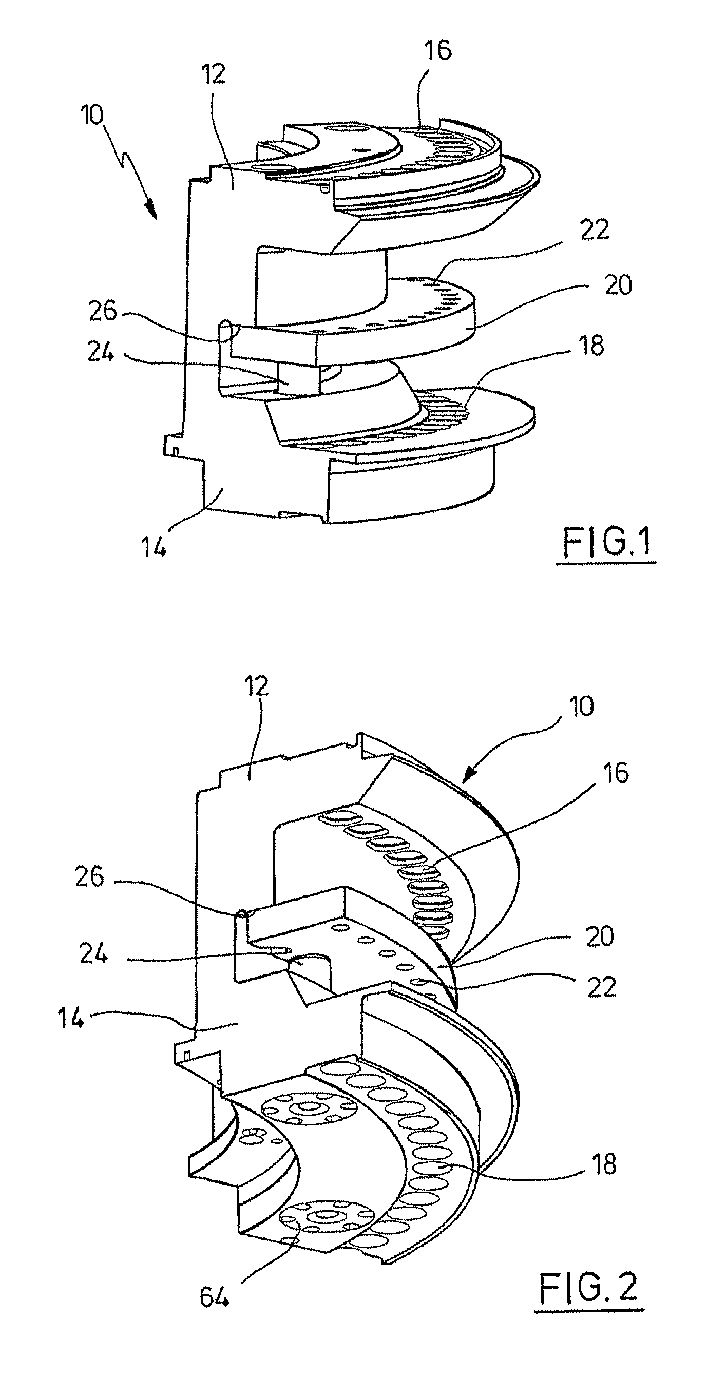
[0028]FIGS. 1 and 2 show a segment of a rotor 10 for a tablet press, like the same is generally known in the state of the art. The rotor has an upper punch guide 12 and a lower punch guide 14 which have guide bores 16 or 18, respectively, which receive not shown compression punches. Only as an example, concerning the accommodation of the compression punches it is referred to the already mentioned DE 10 2004 040 163, the entire contents of which is incorporated herein by reference. The rotor 10 is made to rotate by a not shown drive motor. According to the lastly mentioned document, the motor can be integrated into the rotor 10. The rotor 10 is rotatably mounted on a pillar of ...


PUM

PropertyMeasurementUnit
perimeter distanceaaaaaaaaaa
heightaaaaaaaaaa
processingaaaaaaaaaa

Abstract

A tablet press with a rotor, which is rotatably mounted in a stand of the tablet press and which has an upper punch accommodation for the upper punches and a lower punch accommodation for the lower punches of the tablet press, as well as a die plate with a series of die bores which are aligned with the upper and the lower punches, wherein the die plate consists of at least two ring segments which can be attached on the rotor by means of a fastening device, wherein clamping elements are arranged in axis parallel passages of the rotor spaced apart in the perimeter distance, which act against the ring segments from the bottom side and clamp against an abutment surface of the rotor, characterized in that at least one drive device for the clamping elements is arranged in the stand of the tablet press, with a coupling element adjustable in the height, which can be selectively set into engagement with the lower end of the clamping element.

Description

CROSS-REFERENCE TO RELATED APPLICATIONS[0001]Not applicable.STATEMENT REGARDING FEDERALLY SPONSERED REASEARCH[0002]Not applicable.BACKGROUND OF THE INVENTION[0003]A typical tablet press is a so-called rotary press. If it is dealt with tablet presses above and below, of course such rotary presses are also meant by which arbitrary other pressed articles can be produced, like in the foodstuff-, washing agent- or other fields, for instance.[0004]The typical construction of a rotary press is to mount a rotor in a stand, wherein the rotor has bores for the guides of upper and lower punches, between which a die plate is arranged with die bores with which the punches co-operate during the circulation of the rotor. The compression punches are actuated by compression rollers in compression stations, and guided outside of the same via control cams.[0005]The rotor is driven by a suitable drive motor. In this context, it has also become known to integrate an electric motor into a rotor, wherein ...

Claims


Application Information

Patent Timeline
Patent Type & Authority Patents(United States)
IPC IPC(8): B29C43/08
CPCB30B15/026B30B11/08
Inventor MALICK, DANIELSOLTAU, WOLFGANGGAEDECKE, JOERGRAU, MATTHIAS
Owner FETTE
Why Eureka
Eureka Blog
Learn More