Lens system and optical apparatus

a technology of optical apparatus and lens system, applied in the field of lenses system, can solve problems such as limited resolution

Inactive Publication Date: 2010-01-05
OLYMPUS CORP
View PDF7 Cites 32 Cited by
  • Summary
  • Abstract
  • Description
  • Claims
  • Application Information

AI Technical Summary

Problems solved by technology

These optical systems have a drawback that a resolution is limited due to a diffraction which occurs due to wave nature of light or electromagnetic waves.

Method used


Image

  • Lens system and optical apparatus
  • Lens system and optical apparatus
  • Lens system and optical apparatus

Examples


first embodiment

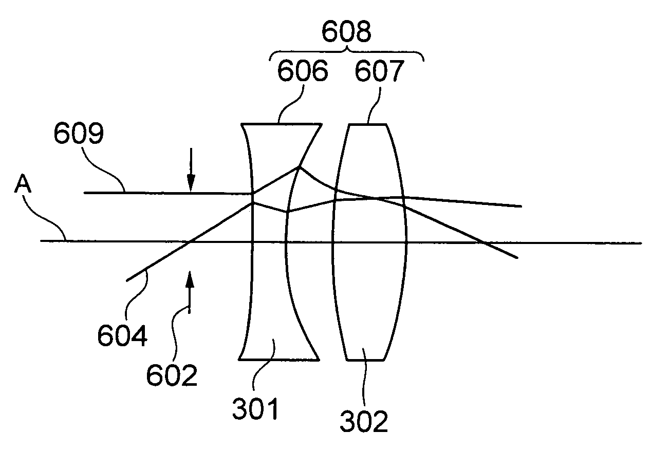
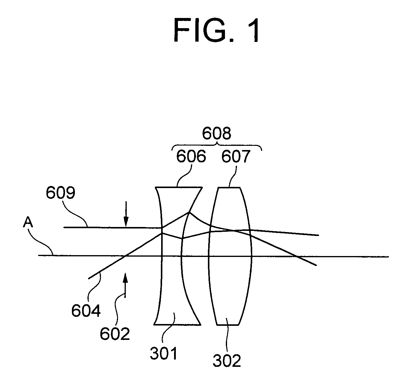
[0031]A first embodiment of the present invention will be described below. FIG. 1 shows an example of the present invention, in which a lens system 608 is shown. In the lens system 608, a lens 606 having a positive focal length f1, which is made of a negative refractive index medium 302 and a lens 607 having a positive focal length f2, which is made of a positive refractive index medium 302 are combined.

[0032]When a relative refractive index of the negative refractive index medium 301 with respect to a surrounding medium is let to be n′1, and a relative refractive index of the positive refractive index medium 302 with respect to a surrounding medium is let to be n′2, then the following expression 105 and expression 106 hold true.

n′1<0  expression 105

n′2>0  expressions 106.

Moreover, the following expression 107 and expression 108 also hold true.

f1>0  expression 107

f2>0  expression 108

[0033]A requirement for eliminating curvature of field when two thin lenses are brought closer is tha...

second embodiment

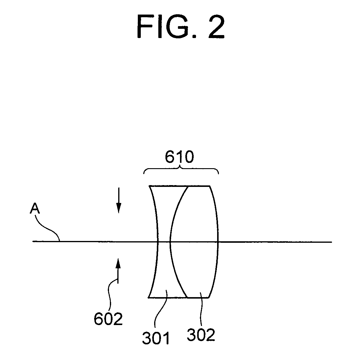
[0037]Next, lens system 613 which includes two lenses 611 and 612, both having a negative focal length as shown in FIG. 3 will be taken into consideration.

[0038]The lens 611 is formed of the negative refractive index medium 301, and the lens 612 is formed of the positive refractive index medium 302.

[0039]When a focal length of the length 611 is let to be f3, and a focal length of the length 612 is let to be f4, it is possible to satisfy the following expression 110 by selecting appropriately f3, f4, n′1, and n′2.

1 / (f3·n′1)+1 / (f4·n′2)=0  expression 110

[0040]Consequently, it is possible to achieve a lens system in which curvature of field due to strong negative power is removed. Here, the following expression 110-1 and expression 110-2 hold true.

f3<0  expression 110-1

f4<0  expression 110-2

[0041]In FIG. 3, the lens 611 and the lens 612 may be cemented by an adhesive. An order of the lens 611 and the lens 612 on the optical axis A may be reversed, since it does not have any effect on Pe...


PUM


Abstract

A lens system includes a first lens which is formed of a medium exhibiting negative refraction, and a second lens having a positive refractive index. Accordingly, it is possible to provide a lens system in which a negative refractive index medium for which a curvature of field is reduced. Moreover, it is also possible to have a lens system in which a lens having a positive focal length and a lens having a positive focal length, which is made of a positive refractive index medium, are combined.

Description

CROSS-REFERENCE TO RELATED APPLICATION[0001]The present application is based upon and claims the benefit of priority from the prior Japanese Patent Application No. 2006-46747 filed on Feb. 23, 2006; the entire contents of which are incorporated herein by reference.BACKGROUND OF THE INVENTION[0002]1. Field of the Invention[0003]The present invention relates to a lens system.[0004]2. Description of the Related Art[0005]Optical systems such as an optical device, an imaging optical system, an observing optical system, a projection optical system, and a signal processing system, in which light or electromagnetic waves are used, and optical apparatuses in which such optical systems are used, have hitherto been known. These optical systems have a drawback that a resolution is limited due to a diffraction which occurs due to wave nature of light or electromagnetic waves.[0006]Therefore, as a technology for realizing an image formation beyond this diffraction limit, using a negative refracti...

Claims


Application Information

Patent Timeline
Patent Type & Authority Patents(United States)
IPC IPC(8): G02B9/04
CPCB82Y20/00G02B1/005G02B1/007G02B9/04G02B27/0025
Inventor NISHIOKA, KIMIHIKO
Owner OLYMPUS CORP
Why Eureka
Try Eureka