System and method for minimizing power consumption for an object sensor

a technology of object sensor and power consumption, applied in the field of object sensor technology, can solve the problem of needless power expenditure for continuous remaining in an operational mod

Active Publication Date: 2010-01-05
SYNAPTICS INC +1
View PDF12 Cites 120 Cited by
  • Summary
  • Abstract
  • Description
  • Claims
  • Application Information

AI Technical Summary

Problems solved by technology

However, continually remaining in an operational mode requires a needless e...

Method used


Image

  • System and method for minimizing power consumption for an object sensor
  • System and method for minimizing power consumption for an object sensor
  • System and method for minimizing power consumption for an object sensor

Examples


Embodiment Construction

[0012]FIGS. 1 through 3, discussed below, and the various embodiments used to describe the principles of the present invention in this patent document are by way of illustration only and should not be construed in any way to limit the scope of the invention. Those skilled in the art will understand that the principles of the present invention may be implemented in any type of suitably arranged object sensor control circuitry.

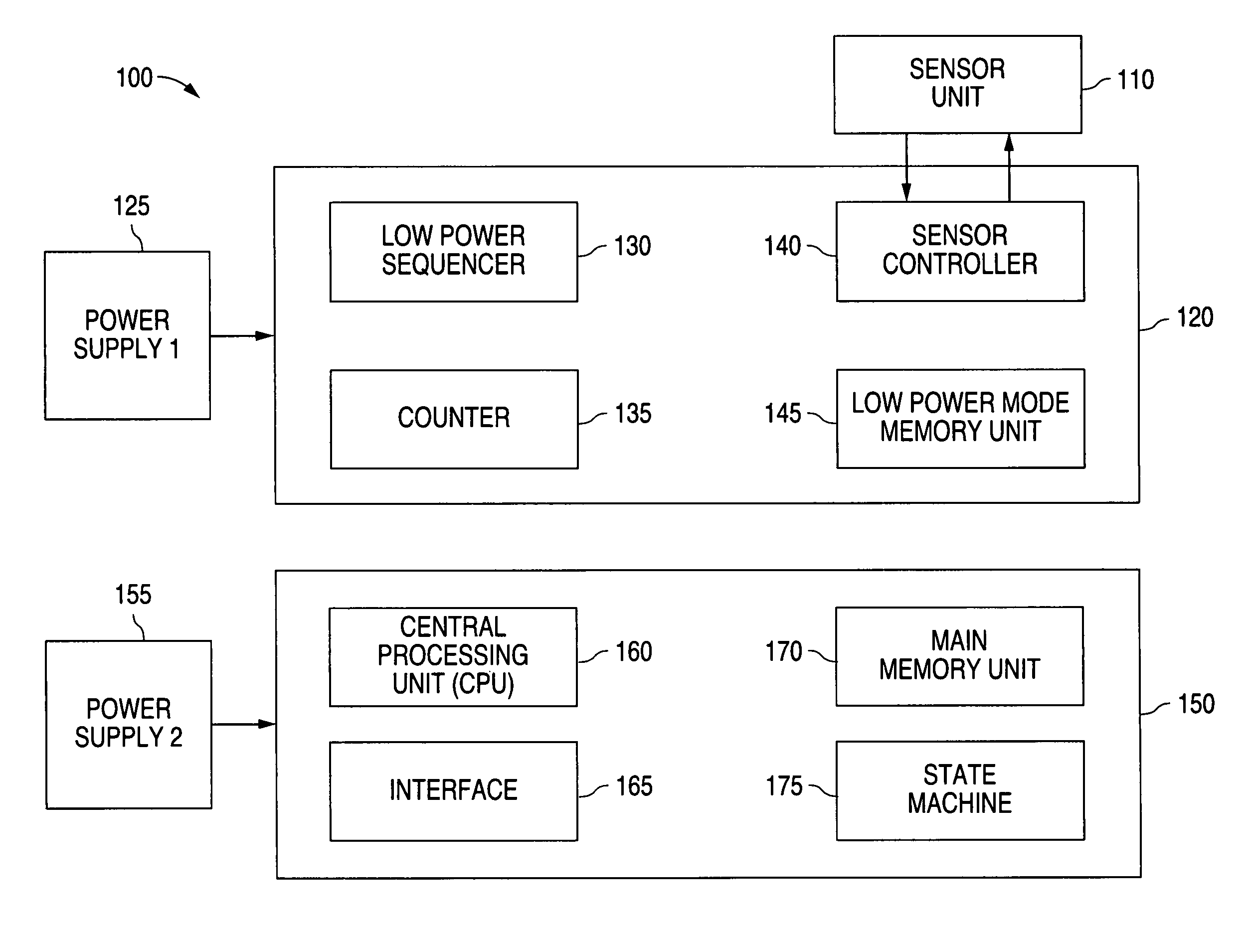
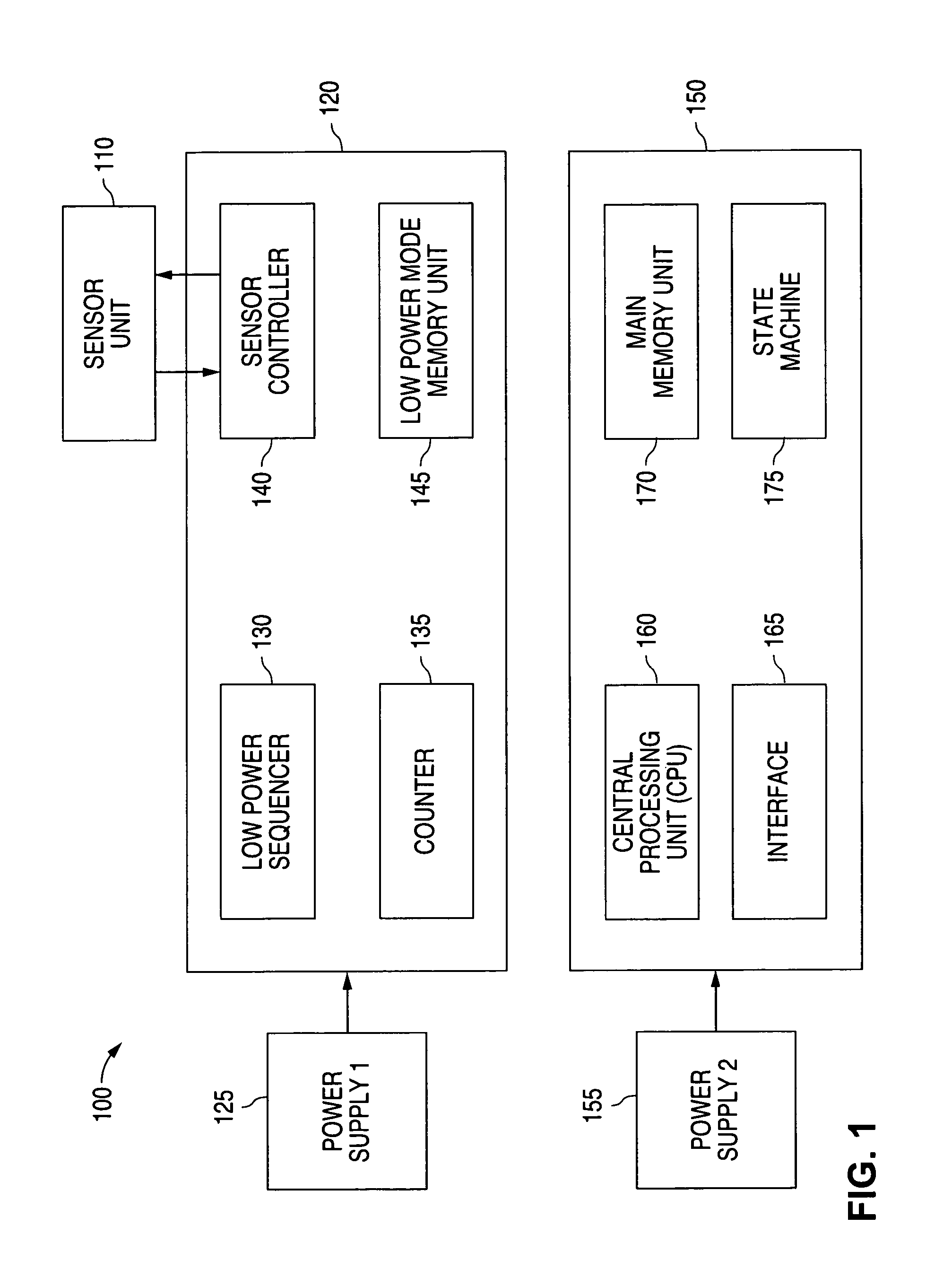
[0013]FIG. 1 illustrates a block diagram 100 of an advantageous embodiment of a circuit of the present invention for providing low power consumption for an object sensor. The object sensor is designated with reference numeral 110. In one advantageous embodiment of the invention, the object sensor 110 is capable of detecting the presence of a finger for the purpose of recording fingerprint information from the finger.

[0014]As shown in FIG. 1, the present invention comprises low power control circuitry 120 and main circuitry 150 for operating the sensor unit 110. ...


PUM


Abstract

A system and method is disclosed for minimizing power consumption of a sensor unit that is capable of detecting an object. Main circuitry operates the sensor unit in a high power mode of operation when the sensor unit detects an object. Low power control circuitry operates the sensor unit in a low power mode of operation when the sensor unit does not detect an object within a pre-determined period of time. The low power control circuitry also comprises a counter to periodically determine when to restore the sensor unit to a high power mode of operation. One advantageous embodiment of the sensor unit is a fingerprint sensor unit for detecting a finger to obtain fingerprint information.

Description

TECHNICAL FIELD OF THE INVENTION[0001]The present invention is generally directed to technology for object sensors and, in particular, to circuitry for providing low power consumption for an object sensor.BACKGROUND OF THE INVENTION[0002]An electronic sensor unit is required to remain operational during the time that the sensor unit is waiting to receive an object to sense. For example, consider a sensor unit that is designed to sense the presence of a finger and obtain fingerprint information from the finger. When a person places a finger on the sensing site of the sensor unit, the sensor unit must be operational in order to perform the sensing function. This means that the sensor unit must continually remain in operational mode.[0003]However, continually remaining in an operational mode requires a needless expenditure of power when there is no object present for the sensor unit to detect. Because a sensor unit may be used in a battery operated system for extended periods of time, ...

Claims


Application Information

Patent Timeline
IPC IPC(8): G01R21/00G01R21/06G06K9/00G06T1/00G06T7/00G06V40/13
CPCG06K9/00013G06V40/13
Inventor GETZIN, LAWRENCENELSON, RICHARD B.JANDU, JASWINDER S.ERHART, RICHARD ALEXANDER
Owner SYNAPTICS INC
Why Eureka
Try Eureka