

Method for providing auxiliary power to an electric power plant using fischer-tropsch technology
a technology of auxiliary power and electric power plant, which is applied in the direction of machines/engines, combustible gas purification/modification, hydrocarbon oil treatment products, etc., can solve the problems of rapid variability in power generation, rapid variability in demand during the day, and power variances can prove problematic, so as to achieve “smooth out” power production with time
- Summary
- Abstract
- Description
- Claims
- Application Information
AI Technical Summary
Benefits of technology
Problems solved by technology
Method used
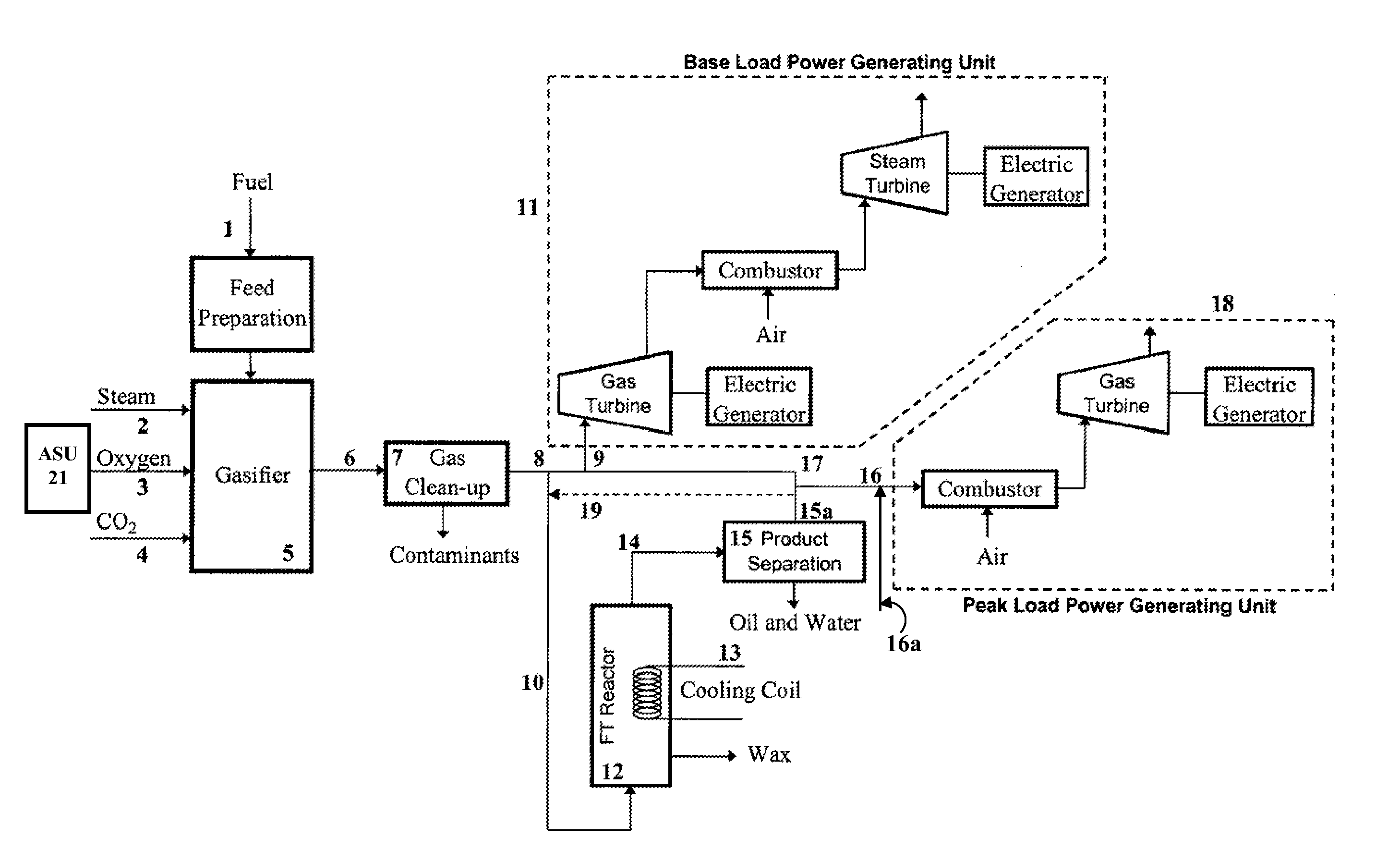
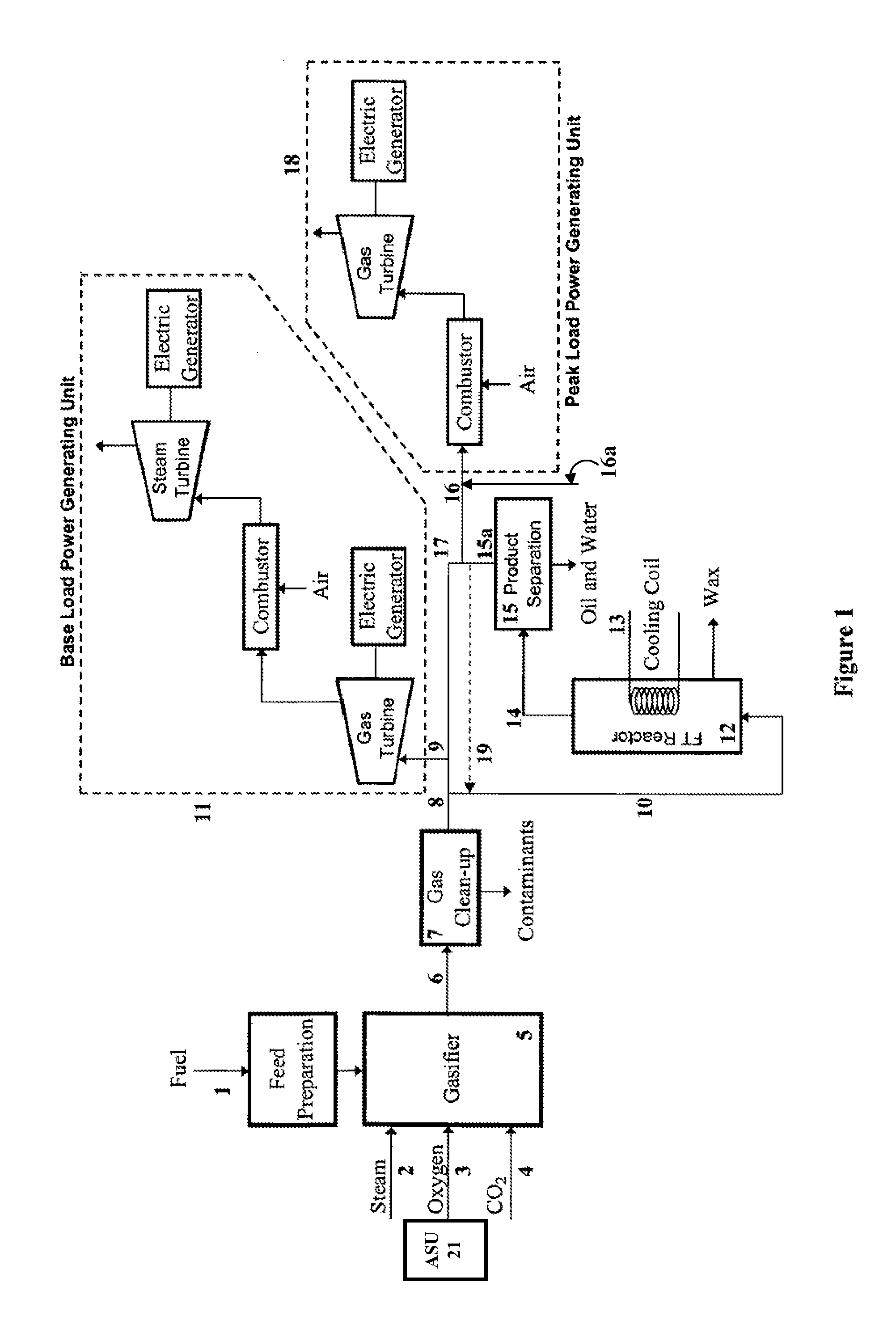
Image

Examples
example 1a
[0025]This example shows the calculated performance of the FT system operating at a high CO conversion and a high alpha for a single pass operation. The quantities of electrical power from tail gas and naphtha and diesel fuel producible under the stated operating conditions are set forth in Table 1. For this example, the following FT parameters are considered:[0026]Pressure=2.8 MPa[0027]α1=0.69[0028]CO Conversion=85%[0029]Temperature=255° C.[0030]α2=0.955[0031]CO2 Productivity=0.42
example 1b
[0032]This example shows the effect of recycling 80% of the tail gas under the operating conditions of Example 1a. The resulting quantities of tail gas, naphtha, which represent the amount of electrical power producible, with diesel fuel are set forth in Table 1.
[0033]
TABLE 1QuantityNo TG Recycle80% TG RecycleFT ProductExample 1aExample 1bTail Gas (Mwe)23.214.0Naphtha (Mwe)13.014.8Diesel (BPD)15981816
example 2a
[0034]This example shows the calculated performance of the FT system operating at a lower temperature and therefore at a lower CO conversion, but with a high alpha catalyst as assumed in Example 1. The quantities of electrical power, represented by the tail gas and naphtha values, and diesel fuel producible under the stated operating conditions are set forth in Table 2. For this example, the following FT parameters are considered:[0035]Pressure=2.8 MPa[0036]α1=0.69[0037]CO Conversion=22%[0038]Temperature=225° C.[0039]α2=0.965[0040]CO2 Productivity=0.35
PUM
 Abstract
Description
Claims
Application Information