Emergency encapsulated lift system

a lift system and encapsulation technology, applied in waterborne vessels, special-purpose vessels, vehicles, etc., can solve the problems of life and property lost on the water, system effectiveness, sailboats, recreational and commercial vessels and equipment alike are in danger of sinking, etc., and achieve the effect of large displacemen

Active Publication Date: 2010-01-12
SCHMITT DARRIN JOHN
View PDF11 Cites 7 Cited by
  • Summary
  • Abstract
  • Description
  • Claims
  • Application Information

AI Technical Summary

Benefits of technology

[0007]Preferred embodiments of the present invention provide buoyancy and stabilization to the marine or aircraft vessel or other desired equipment by displacing sufficient water to keep the vessel afloat at or near it's intended waterline or at an intended displacement level for other applications until either help can arrive, repairs can be performed, or until the vessel can be brought safely to port. Because some embodiments of the invention are deployed below the waterline 14 and some bladder designs are cylindrical, large displacements may be achieved. Embodiments maintaining the vessel at or near an intended waterline 14 enable continued operation of the vessel, giving personnel needed time and peace of mind to react to the emergency. Preferred embodiments of the present invention are applicable to any vessel design regardless of type or size.

Problems solved by technology

Every year, life and property are lost on the water.
Power and sail, recreational and commercial vessels and equipment alike are all in danger of sinking due to loss of buoyancy.
However, such systems are effective only so long as the capacity of the pumping system exceeds the rate at which water is coming into the vessel.
If the amount of water entering a vehicle exceeds the capacity of the pumps or they fail to dispose the water outside of the vessel, the vessel is doomed to sink.
Previous devices designed to enhance buoyancy have not provided a viable solution for the industry for a number of reasons.
Primarily, they are not designed to be conveniently maintained or tested to ensure constant working conditions.
Many systems cannot both easily fit into the limits of space and provide the amount of buoyancy required to keep a vessel from sinking.
Previous devices also adversely affect the desired efficiency or appearance of the vessels' design and thus their marketability.

Method used


Image

  • Emergency encapsulated lift system
  • Emergency encapsulated lift system
  • Emergency encapsulated lift system

Examples


Embodiment Construction

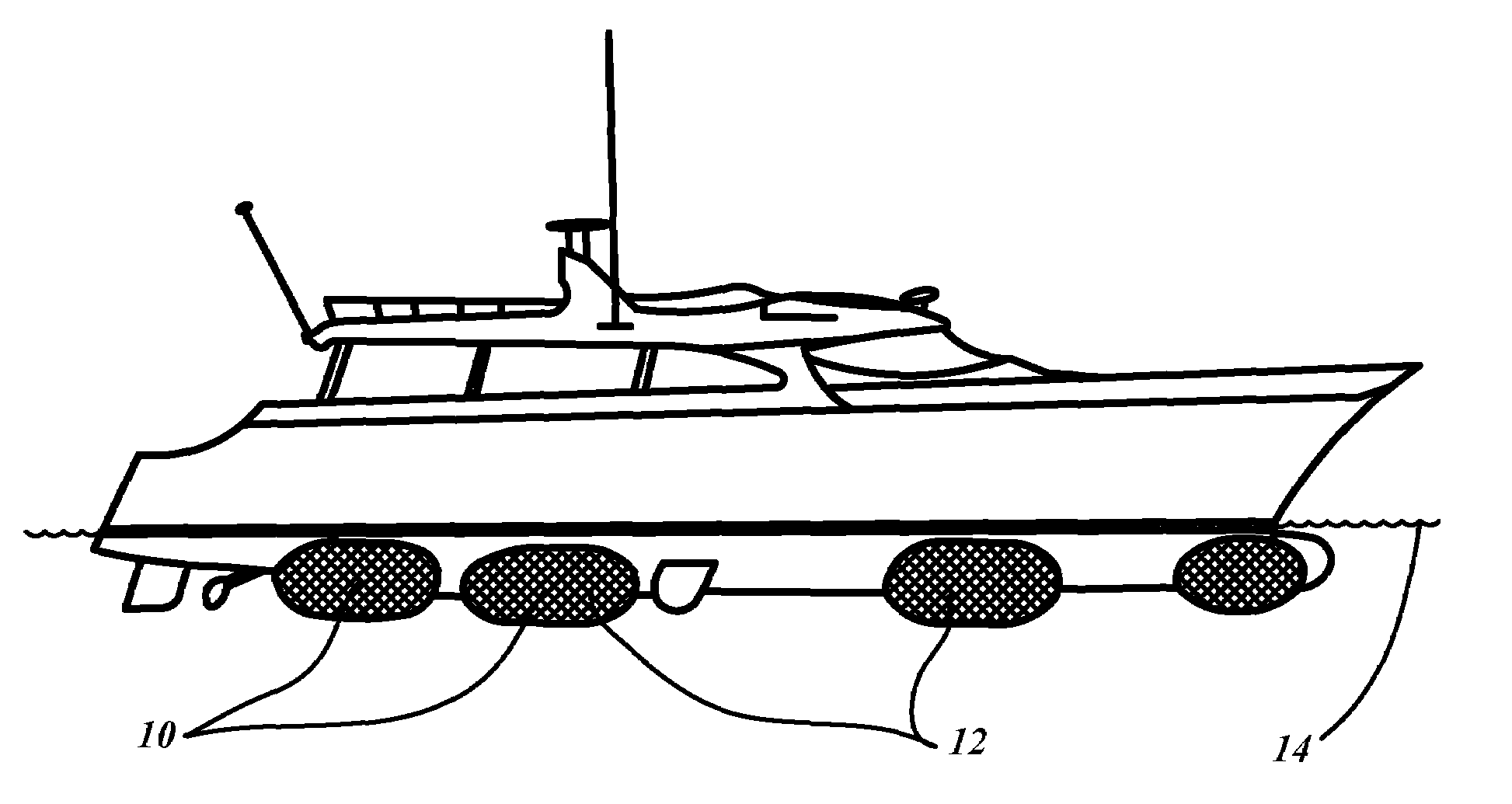
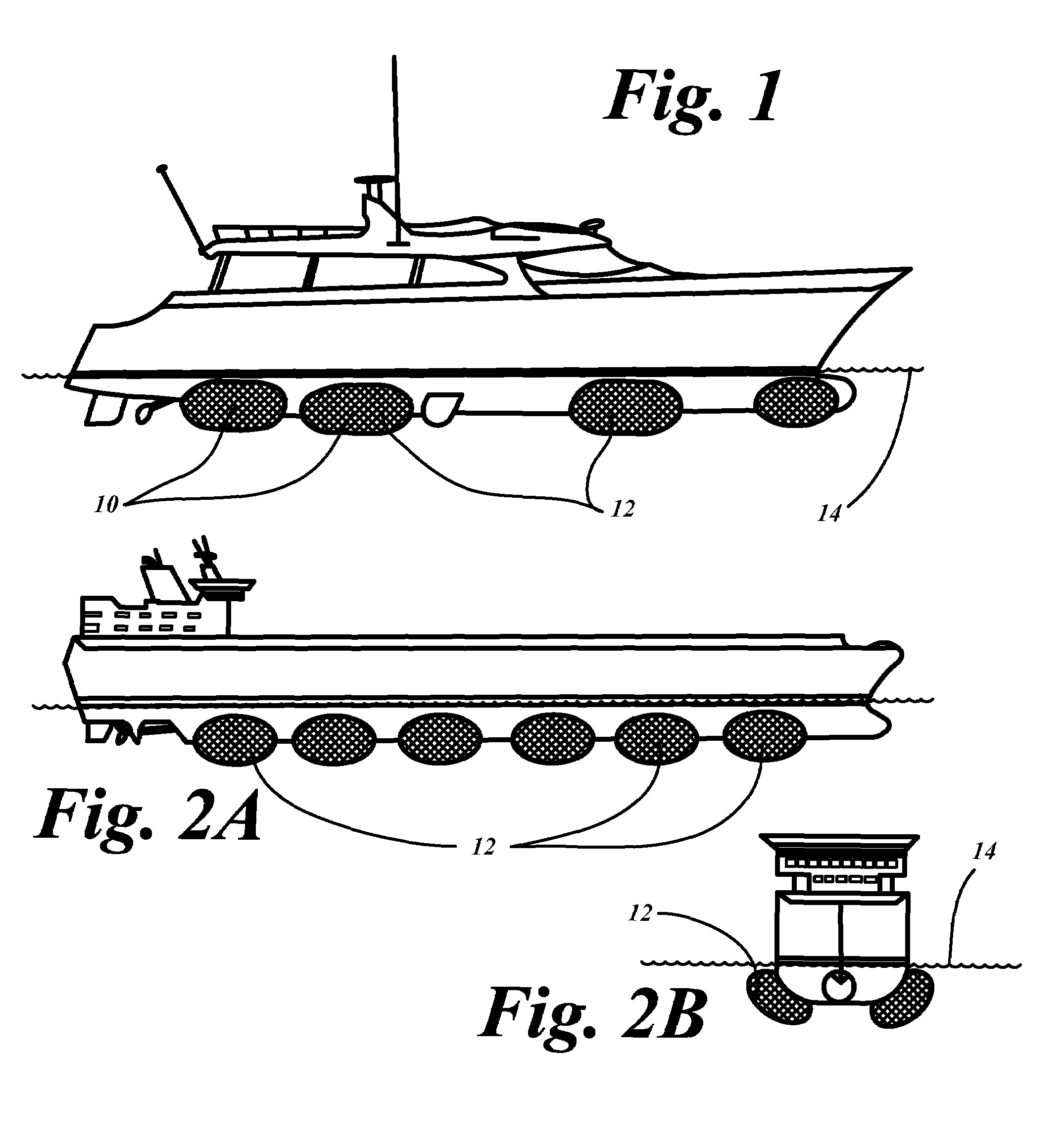
[0025]Referring to FIGS. 1 and 2, a compact encapsulated lift system 10 includes air bladders 12 deployed from air, water, and other, vessels of varying sizes and geometries. For example, as shown in FIG. 1, luxury boat or yacht may deploy four air bladders 12 per side. Typically at least two air bladders 12 per side are used to provide stability. However, even only one or two bladders total may be enough to provide significant benefits. As shown in FIG. 2A, a much larger cargo ship may deploy six or more air bladders 12 per side. The displacement of the air bladders 12 may also be increased based on the size of the vessels to which they mount. As shown in FIG. 2B, the air or foam bladders 12 mount to both sides of the vessel, such as the cargo ship. In the embodiment of FIGS. 2A and 2B, the bladders 12 protrude from the vessel at an angle such that an outer surface of the bladders 12 approximates the orientation of the hull. As is apparent form FIGS. 1 and 2A and 2B, the bladders 1...


PUM


Abstract

A buoyancy lift system having an inflatable bladder with a tether stowed inside a canister secured to a vessel. A sealing member is slidably received within canister and secures to the inflatable bladder. Pressurized gas forces the sealing member and bladder outwardly of the canister. A stop prevents the sealing member from escaping the canister such that the sealing member creates a seal between itself and the canister at an outboard end of the canister. Pressurized gas is forced through a channel in the sealing member into the bladder to increase the displacement of a vessel.

Description

FIELD OF THE INVENTION[0001]This application claims the benefit of Provisional Application Ser. No. 60 / 673,943 filed Apr. 22, 2005, which is hereby incorporated by reference.FIELD OF THE INVENTION[0002]This invention relates generally to a life and property saving devices of the type which can be automatically or manually activated to expel a buoyancy compensation bladder from the interior of a vehicle through an outer wall of a vehicle or from a point of securement to a vehicle into the surrounding water to provide additional buoyancy in the event that the vehicle is in danger of sinking.BACKGROUND OF THE INVENTION[0003]Every year, life and property are lost on the water. Power and sail, recreational and commercial vessels and equipment alike are all in danger of sinking due to loss of buoyancy. In fact most vessels, vehicles or aircraft traveling over water have at one time or another needed buoyancy enhancement. The problem has been somewhat alleviated by the advent of new constr...

Claims


Application Information

Patent Timeline
Patent Type & Authority Patents(United States)
IPC IPC(8): B63B43/10
CPCB63B43/14B63B2043/145
Inventor SCHMITT, DARRIN JOHN
Owner SCHMITT DARRIN JOHN
Why Eureka
Try Eureka