Synchronized four-bar linkages

a four-bar linkage and synchronization technology, applied in the field of synchronized four-bar linkages, can solve the problems of ineffective structural system, inefficiency of basic structural structure, and long setup tim

Active Publication Date: 2010-01-12
RAPID DEPLOYABLE SYST LLC
View PDF29 Cites 32 Cited by
  • Summary
  • Abstract
  • Description
  • Claims
  • Application Information

AI Technical Summary

Benefits of technology

[0008]Further disclosed are means to cause the mechanism, when in its extended state, to become stiff and structural. Fabric elements may be attached to these mechanisms to form rapidly deployable shelters.
[0009]Accordingly, it is an object of the invention to provide a linkage system or mechanism that is adapted for optimum deployment and structural performance.
[0011]A further object of the invention is to provide a linkage system which provides a compact package in its retracted state.

Problems solved by technology

As the size of the tent or shelter increases, the required setup time lengthens.
However, once the structure is deployed, they are less effective in providing an optimum structural system.
This results in a basic structural inefficiency.
Such inefficiency can limit the structural span, lead to increased weight, and prevent efficient packaging.

Method used


Image

  • Synchronized four-bar linkages
  • Synchronized four-bar linkages
  • Synchronized four-bar linkages

Examples


Embodiment Construction

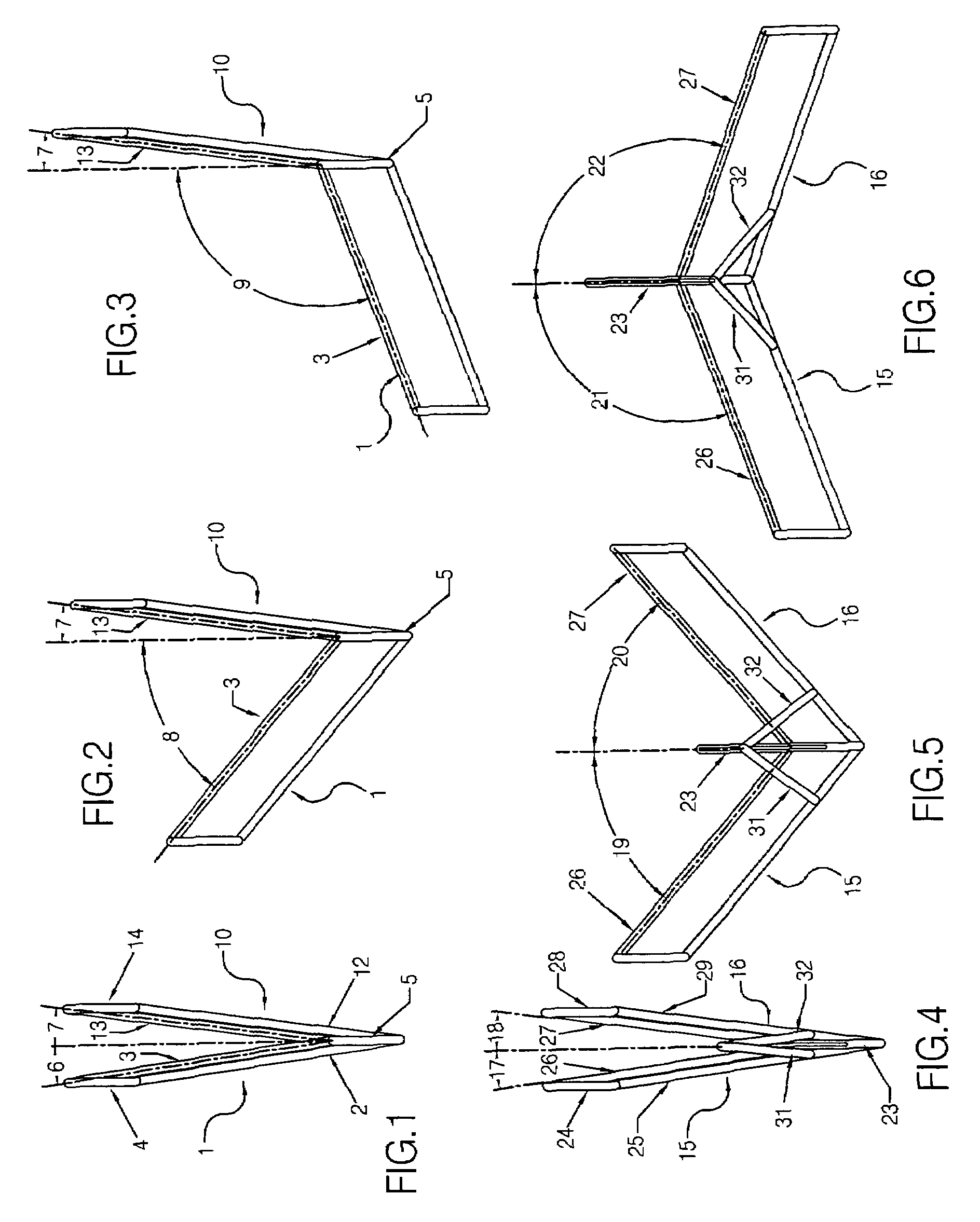
[0082]FIG. 1 shows two linkages 1 and 10 that share a common link 5. Linkage 1 is comprised of four links 2, 3, 4 and 5; linkage 10 is comprised of four links 12, 13, 14 and 5. Linkages 1 and 10 are shown in a contracted position, such that links 3 and 13 form angles 6 and 7 relative to the centerline of common link 5.

[0083]FIG. 2 shows the linkages 1 and 10 whereby linkage 1 has been rotated such that the angle 8 formed by link 3 relative to common link 5 is now changed from the similarly formed angle shown in FIG. 1. Linkage 10 is shown to be in the same position as shown in FIG. 1. Therefore it may be seen that linkages 1 and 10 are capable of moving independently from each other.

[0084]FIG. 3 shows linkage 1 in a further rotated position, whereas linkage 10 is in the same position as the previous two figures.

[0085]FIG. 4 shows two linkages 15 and 16 that share a common link 23. In addition to the four links 23, 24, 25 and 26 that comprise linkage 15, an additional link 31 is show...


PUM


Abstract

A mechanism that is comprised of two or more four-bar linkages is shown. Each linkage shares a common link with each adjacent linkage and the movement of said two or more linkages is synchronized by mechanical means such that said mechanism may move between a collapsed and an extended state. Said mechanical means may be in the form of additional links or geared connections.

Description

[0001]The application claims priority benefit of Provisional Application No. 60 / 644,233, filed Jan. 14, 2005.BACKGROUND OF THE INVENTION[0002]This invention relates to the area of tents and the provision of temporary shelter. Often there is a need to rapidly set up such shelters. Among standard tent designs, the time required to set them up can be substantial. A series of steps is required including laying the fabric out on the ground, inserting and attaching poles, pulling the structure erect, staking it to the ground, and attaching guy ropes for extra stability. As the size of the tent or shelter increases, the required setup time lengthens.[0003]There are various rapidly deployable systems for tents that effectively reduce the setup time. Many of these systems are based on extensible tong linkages, sometimes referred to as scissor linkages. My own U.S. Pat. No. 5,024,031, hereby incorporated by reference as if fully disclosed herein, utilizes such scissor linkages to construct tr...

Claims


Application Information

Patent Timeline
Patent Type & Authority Patents(United States)
IPC IPC(8): E04H15/48
CPCE04H15/48E04H15/52
Inventor HOBERMAN, CHARLESDAVIS, MATTHEW
Owner RAPID DEPLOYABLE SYST LLC
Why Eureka
Try Eureka