Reagent cuvette

a technology of cuvettes and cuvettes, which is applied in the direction of biochemistry equipment, biochemistry equipment and processes, instruments, etc., can solve the problems of large number of patients being unnecessarily subjected to trouble and worry of further unwarranted tests

Inactive Publication Date: 2010-01-12
ODONOVAN MICHAEL
View PDF6 Cites 15 Cited by
  • Summary
  • Abstract
  • Description
  • Claims
  • Application Information

AI Technical Summary

Problems solved by technology

Thus, a large number of patients may be unnecessarily subjected to the trouble and worry of further unwarranted tests beyond the point of care.

Method used


Image

  • Reagent cuvette
  • Reagent cuvette
  • Reagent cuvette

Examples


Embodiment Construction

Brief Description of the Drawings

[0029]The invention will be more clearly understood from the following description of some embodiments thereof, given by way of example only with reference to the accompanying drawings in which:

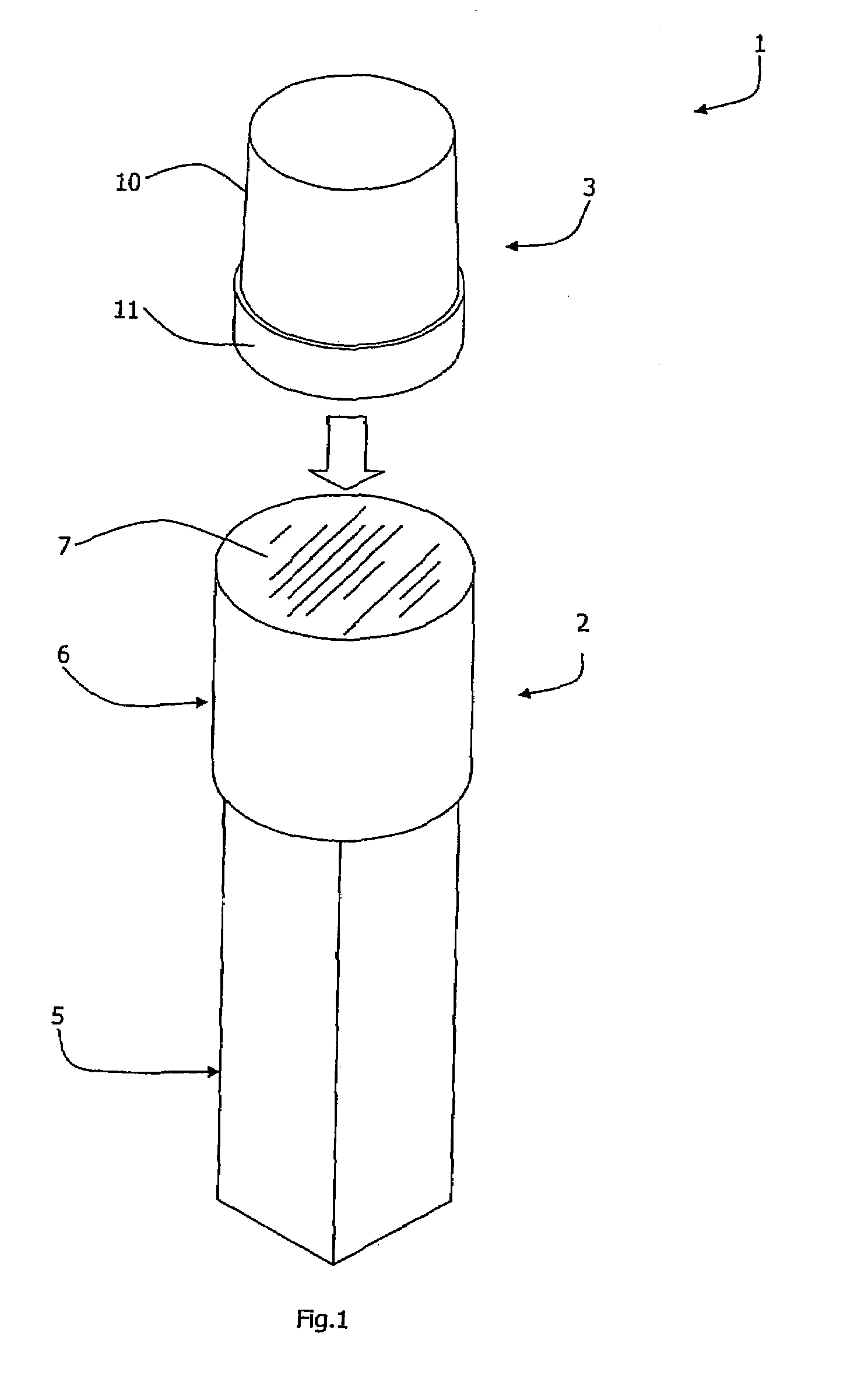
[0030]FIG. 1 is a perspective view of both parts of a reagent cuvette of the invention, and

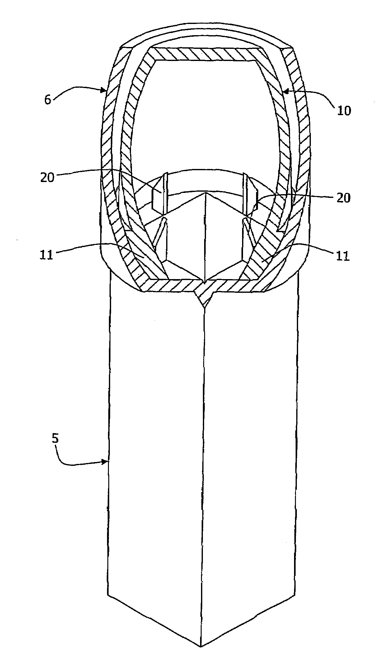
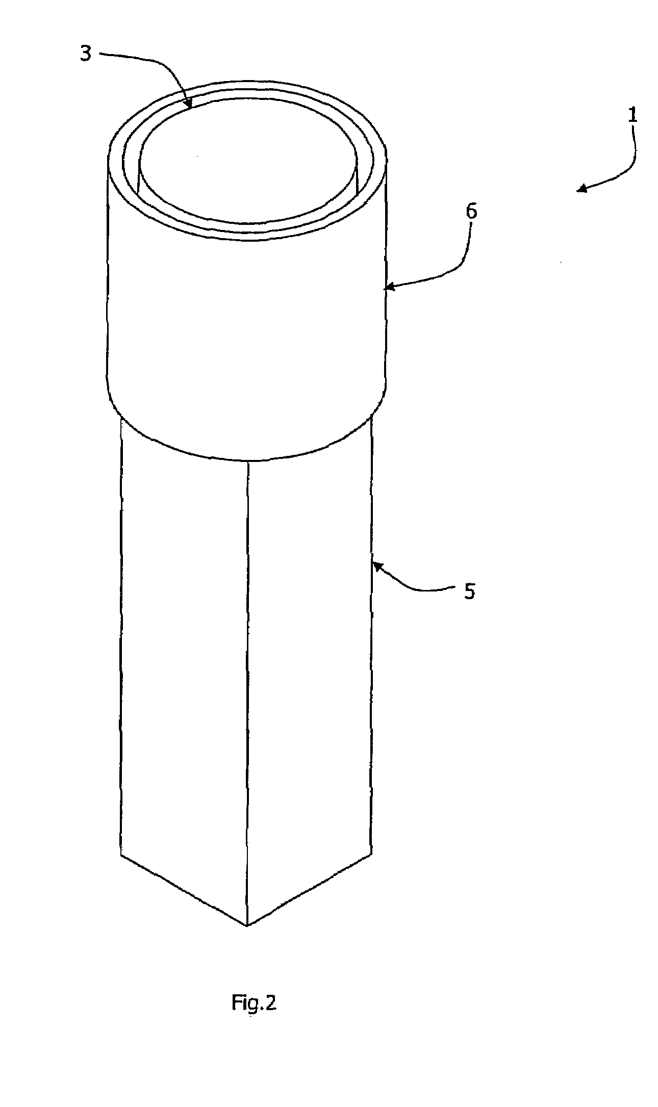
[0031]FIGS. 2, 3, and 4 are perspective, cut-away / sectional, and cross sectional views respectively of the cuvette with both parts together.

DESCRIPTION OF THE EMBODIMENTS

[0032]Referring to the drawings there is shown a reagent cuvette 1 for point-of-care analysis with laboratory accuracy. The cuvette 1 comprises two main parts, namely a first chamber 2 of approximately 64 mm height and a separate second chamber 3. The first chamber 2 and the second chamber 3 are of transparent plastics material. Both parts of the cuvette are of moulded plastics construction.

[0033]The first chamber 2 comprises an inspection part 5 and a socket 6 for receiving the chamber 3 in use, as desc...


PUM

PropertyMeasurementUnit
heightaaaaaaaaaa
transparentaaaaaaaaaa
thicknessaaaaaaaaaa

Abstract

A reagent cuvette has a first chamber with an inspection part and a socket, and a second chamber. The socket has four spikes at its base. Both chambers are sealed with a membrane. At the point-of-care the foil membrane of the first chamber is peeled away by the therapist (typically general practitioner doctor). A sample, such as blood, is added to the chamber using a pipette or other device to provide a verifiable quantity of sample. This provides a mixture of a buffer reagent supplied in the chamber and the sample injected into the inspection chamber at the point of care. The chamber is then inserted into the socket by gently pressing it down so that its foil membrane is broken by the spikes. This causes the starter reagent to drop down from within the second chamber into the inspection part of the first chamber. The inspection part is then inserted into an optical inspection instrument for analysis of the two reagents and the sample mixed together.

Description

[0001]This is a continuation of PCT / IE04 / 000162 filed Nov. 18, 2004 and published in English, claiming benefit of U.S. provisional application No. 60 / 523,104, filed Nov. 19, 2003.FIELD OF THE INVENTION[0002]The invention relates to a reagent cuvette for sample analysis.PRIOR ART DISCUSSION[0003]At present, there is often a two-stage analysis of samples, namely point-of-care and laboratory analysis. Typically, the point-of-care analysis is performed using “dry chemistry” techniques. This is because such techniques are simple and convenient to perform: a sample being placed on a strip coated with a dry reagent and the strip being inserted into an inspection instrument.[0004]The laboratory analysis is typically performed using “wet chemistry” techniques in which controlled volumes of fluid sample and reagent(s) are admixed and optically inspected. The “wet chemistry” techniques are regarded as being full and reliable tests, where the “dry chemistry” techniques are reliable only for scr...

Claims


Application Information

Patent Timeline
Patent Type & Authority Patents(United States)
IPC IPC(8): B01L3/00B01L3/02C12M1/24C12M1/34C12M3/00C12M3/04B01L3/14G01N21/03
CPCB01L3/502B01L3/5082B01L3/50825B01L3/5635G01N21/03B01L2200/026B01L2200/16B01L2300/044B01L2300/047B01L2300/0672B01L2400/0683G01N2021/0321G01N2021/0325G01N2021/0364G01N2201/0245
Inventor O'DONOVAN, MICHAEL
Owner ODONOVAN MICHAEL
Why Eureka
Try Eureka